If you bought one of my modules recently, it is also worth looking at the how-to project page for this module 🙂
There is a new method available to flash the module initially via ESPhome webtools. Therefore I created a new GitHub repository ESPhome-KM271-WiFi based on jesserockz cool template. The firmware is build with github workflows and a release is created containing all, factory and OTA images.
Find a video how to assemble the board on my YouTube channel.
The PCB for this project (0.0.5) was sponsored by PCBway. 
And I really liked what I received. I ordered a few times in the past and always received excellent PCBs from this manufacturer. And also the engineering service is best in class. They ask you what to do, if any problem occurs and either you send new gerbers or they fix it themselves (if possible by editing the gerber). Sooner or later, I’m sure, I’ll also try their assembly and milling services…
If you want to read an article about preparing your data for PCBway, stay tuned, it will be also linked here.
Version 0.1.0 is available soon (mid of February)
Breaking News From „Under the Ground“
2025-01-13 New bunch ordered and new GitHub repo
I ordered a new bunch of PCBs to arrive approx mid of February. I also created a new repo on GitHub to handle automated builds of the KM271-WiFi firmware using jesserockz cool esphome project template.
2024-01-24 Out of Stock
As some of you already realized, my Tindie store is out of stock since beginning of the year. But the waitlist is growing again and it allocated already 45 people interested in the module. As soon as it grows beyond 50 people, I’ll order a new batch (of 100). My assumtion is, that this goal is reached about end of this month. As soon as I order, the lead time is around 4-6 weeks, mostly depending on the production lead times and the components availability. Assuming I order on February, 1st, I expect the shippment to arrive beginning of March.
For all that can not wait, I still have bare PCBs (of 0.0.5 and 0.0.7), but soldering needs to be done by yourself.
2023-04-29 New version available (since a few weeks)
OK, I totally forgot to update this post 😋 The modules arrived a few weeks ago and I already sent our more than 50 pieces (of the 100 I ordered). So there are currently plenty of it left to be ordered on Tindie.
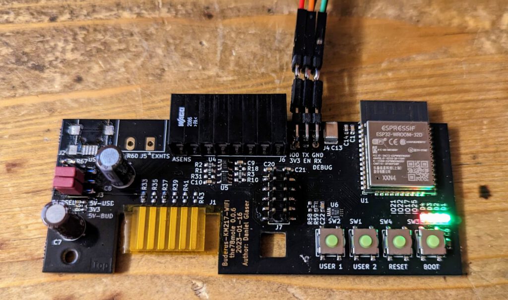
2023-03-04 QC succeeded
Today I received the QC images of the assembled PCBs. They seem to be correct and production will continue for the remaining parts. From my experience, they will be finished within next week and delivery will be approximately in two weeks. I’m totally excited to receive them 😛
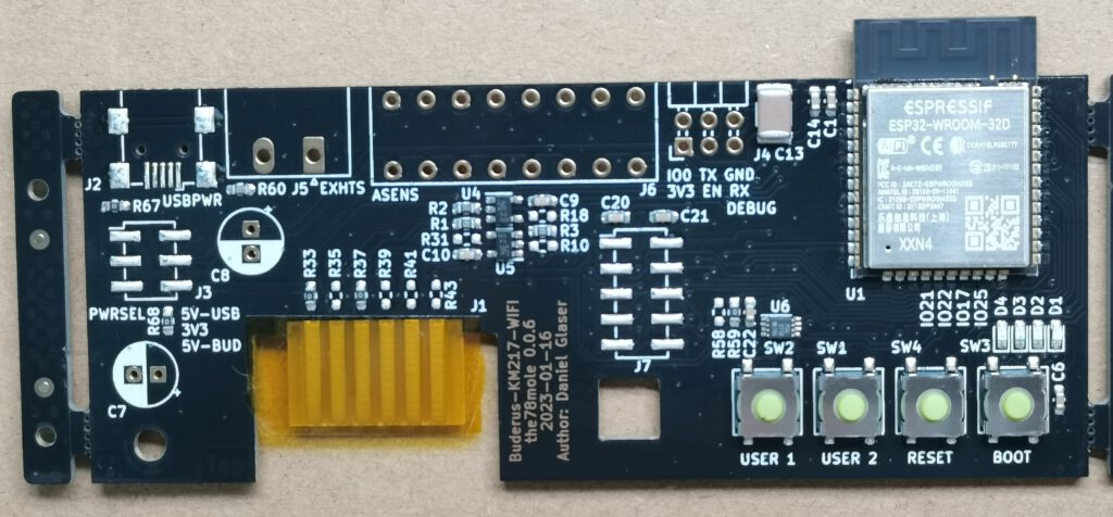
2023-02-18 In Production
The assembled PCBs are still in production. Some parts had longer lead times. Estimated arrival of the hardware is currently second half of March.
2023-01-16 Sneak Preview
A little later than planned, but here is a sneak preview of the 0.0.6 board, including analog inputs for Pt- or NTC-type temperature sensors, a OneWire break-out and extension, a I²C/SPI-extension header, USB external power supply option and a jumper to select power supply options.
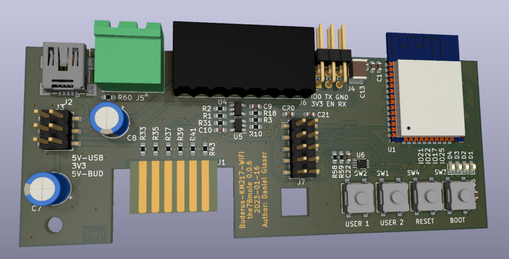
I’ll order the new batch end of January, so it can get delivered until end of February.
2022-12-06
the functionality of the km271 gets more and more fantastic. I can now instruct my heating system to switch the hot water mode from on to off and auto (following the heating day and night modes). I can also set the hot water target emperature and do way more stuff. The Buderus Logamatic soon will be simply an old Relay-Box with Temperature-Sensor-Circuits 🤣 All sensors I wished are now available.
And since I have only 10 of my 50 modules left after a single month, time comes closer to update the hardware again and implement a simple onewire interface (as many people suggested). I’ll add the hardware for the simple MCU-pin variant, but also to use an I2C-1wire-interface-IC from Maxim. The latter just produces way more clean 1-wire-signals, has Power-Pull-Up and therefore runs on way longer lines (to my experience). The drawback of the I2C solution is, that it is not yet integrated into ESPhome… Digging challenge accepted 😛
Sven published his firmware on GitHub. It is really worth looking at it, since it also contains writing commands to the buderus heating system. Thanks so much Sven!!!
ESPhome Firmware also received georgeous updates from Sven, Jens and Bascht. They added the sensors finally, two write params and now it is easy to add more.
Motivation
As you all know, my home is stuffed with more sensors than the ISS, but I still have some heating installation burning oil… and it stops working quite often (approx. once a week), raising an error from the flame sensor that easily can be commited and everything is working fine for the next days or weeks. In summer-time this is only nasty, and sometimes when I want to take a shower, I realize, that there is no hot water left, the boiler decided to raise an error and I (a) need to wait for the water to heat up or (b) need to take a cold shower if I’m in a hurry… In wintertime, this is worse, because not only the hot water, but also the whole heating is stopped. Not a satisfiying situation 🙁
While I’m planning to renovate the house and switch to some heat pump installation, there is still plenty of time to take cold showers. If I only would know that the heating has an error in advance or when the error just have been raised… For sure, I could simply attach some binary sensor to the flame detector and make an alarm bell ring, by using some analog interface or simply a 230 VAC relay. But this would be way too easy…
My heating system is running a Buderus Logamatic 2107 M main control unit and this has some free slot for a so called KM271 communication module… In my control unit, it is unpopulated 🙁
I also recently found out, that Buderus sells a unit called Logamatic web KM200 for just 270 bucks (€). Man, this is cheap! And you can access it with your smartphone, but obiously get a nice vendor lock-in, everybody running a smart home is excited about.
Here are some additional information that helped me to dig through:
Remote Reverse Engineering
Since I have no KM217 available, I need to do the reverse engineering without some real hardware. For sure I could buy one, but the effort to dongle it to my smart home would not be much less and I don’t want to spend 100 € for a nasty level converter and some chicken feed, only because it has the buderus sign on it…
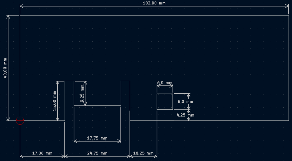
OK, I found some pictures online of top and bottom sides of the original KM271 module. Then I compared my measurements of the slot inside the LM 2107 with the sizes from the photos and started to draw the PCB outline…
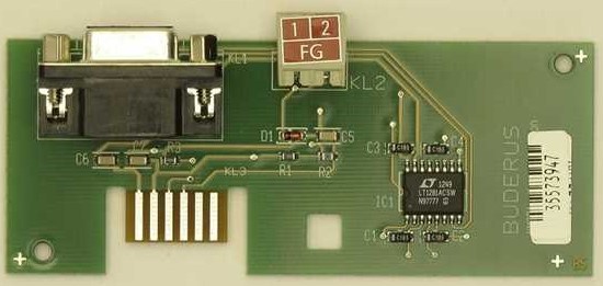
Some handy online tool to take measurements out of photos can be found here.
What you can also see on the photo is the main IC on this board, namely the LT1281ACSW (datasheet), which is a simple 5V-to-EIA/RS-232 level converter. From it’s datasheet, we can see, what are the supply pins and which are the relevant signals. The FG-Connector is just to wire an exhaust probe head, which is irrelevant for us.

Tracing some signals…


I also found some information on mikrocontroller.net about some possible pinout.
OK, we have quite some information collected about the module and now we can start to create some PCB…

Here come some details to the mechanics and to the the circuit, we want to develop. At first, I really don’t need a EIA/RS-232 signal to connect it with my smart home. What I really need is some wireless network connection. So, I decided to implement some ESP32 directly. With this, I can easily flash ESPhome, run OTA updates, push decoded data to MQTT or whatever I deserve, with a simple click of my fingers (or some more clicks, but not many 🙂 ).
Schematic & PCB Design
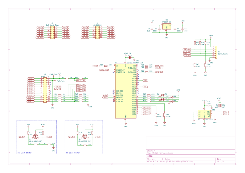
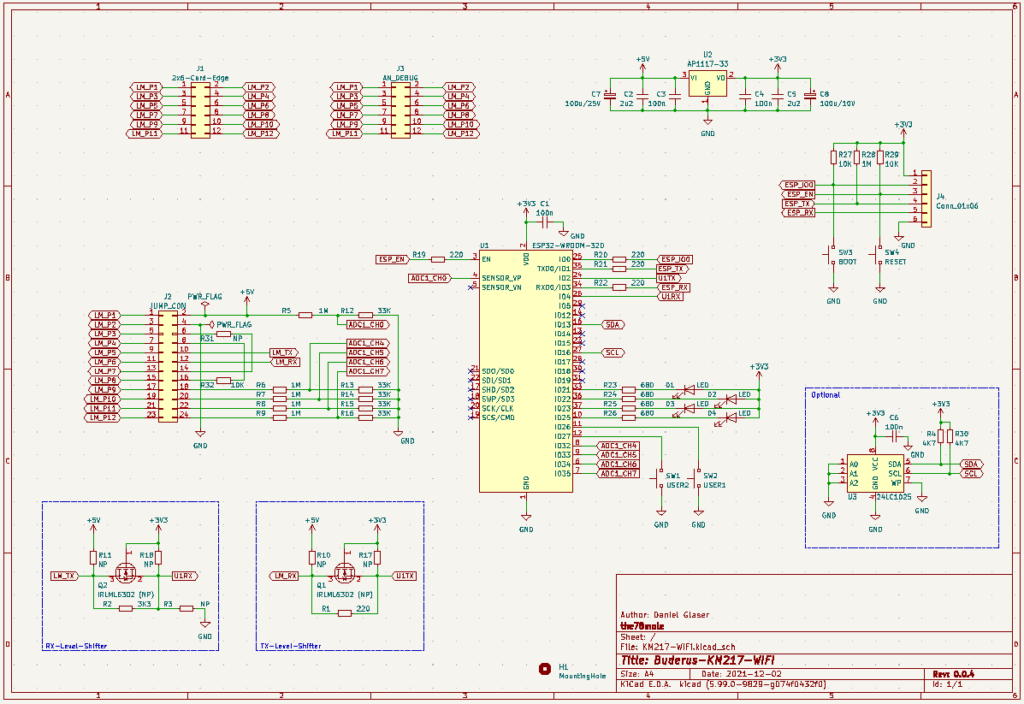
Given these requirements, we will use an ESP32 (WROOM-32D module). We will also need to shift the levels of the 5V-TTL serial interface to comply with 3.3V of our ESP32 and vice versa and we also need to generate 3.3V from 5V for our supply…
For the serial interface, getting down from 5V to 3.3V could be easily done with a resistor. Ideally, the heating control will accept the 3.3V as a high level, but to make sure, we will put a simple MOSFET level shifter in between.
On the other side, we are not yet sure, if we identified the signals correctly. To accompany that, we added a connector 1:1 connecting the signals of the blade connection to some standard pin header, so we can easily add a flat ribbon cable to it and use a second board to get a simple „range extender“ for measuring every signal without a risk of shorting them.
Additionally, we add some dual row header. On this header, we can use jumpers if we guessed correctly and jumper wires, if we got it wrong.
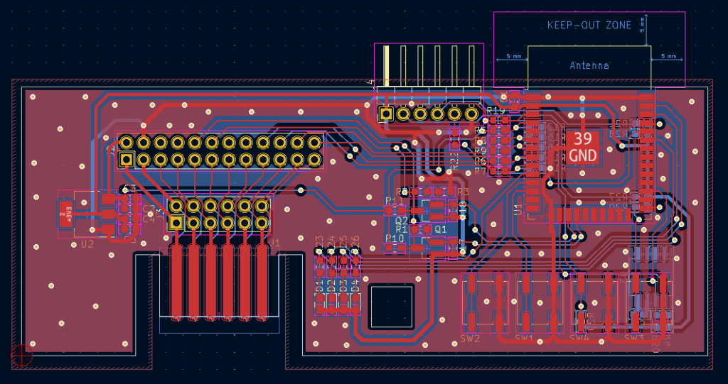
Latest Design
Historic Designs
OK, here is the first shot of the design:
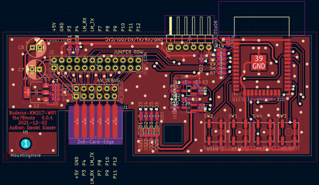
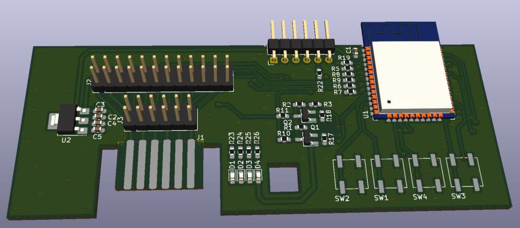
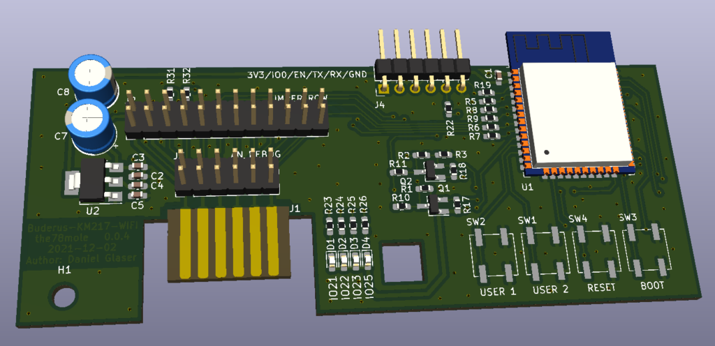
My Own PCBs
Latest Order on PCBway for V0.1.0
I ordered 200 pieces of assembled boards on PCBway. I’ll keep you updated as soon as they will arrive. I estimate, it will be around mid of February.
Historic Versions
I ordered a bunch of PCBs (Think BMS, Think-Balancer-Adapter, ESP32-18650-Humidity-Temperature-Board and this KM271-WiFi Adapter) on Juli, 27th 2021 from PCBway. And it was lightning fast… Today (August, 4th 2021), one week after I placed my order, it was delivered by FedEX-IP. As I mention in my other post on designing PCBs (coming soon), do not use DHL. It is expensive and they will draw another 12,50 € from you for a short tie credit of the taxes and duty.
You can order the PCB and the parts from my tindie shop.
I also want to thank PCBways, to support my projects with sponsored PCBs. And also the ones I paid
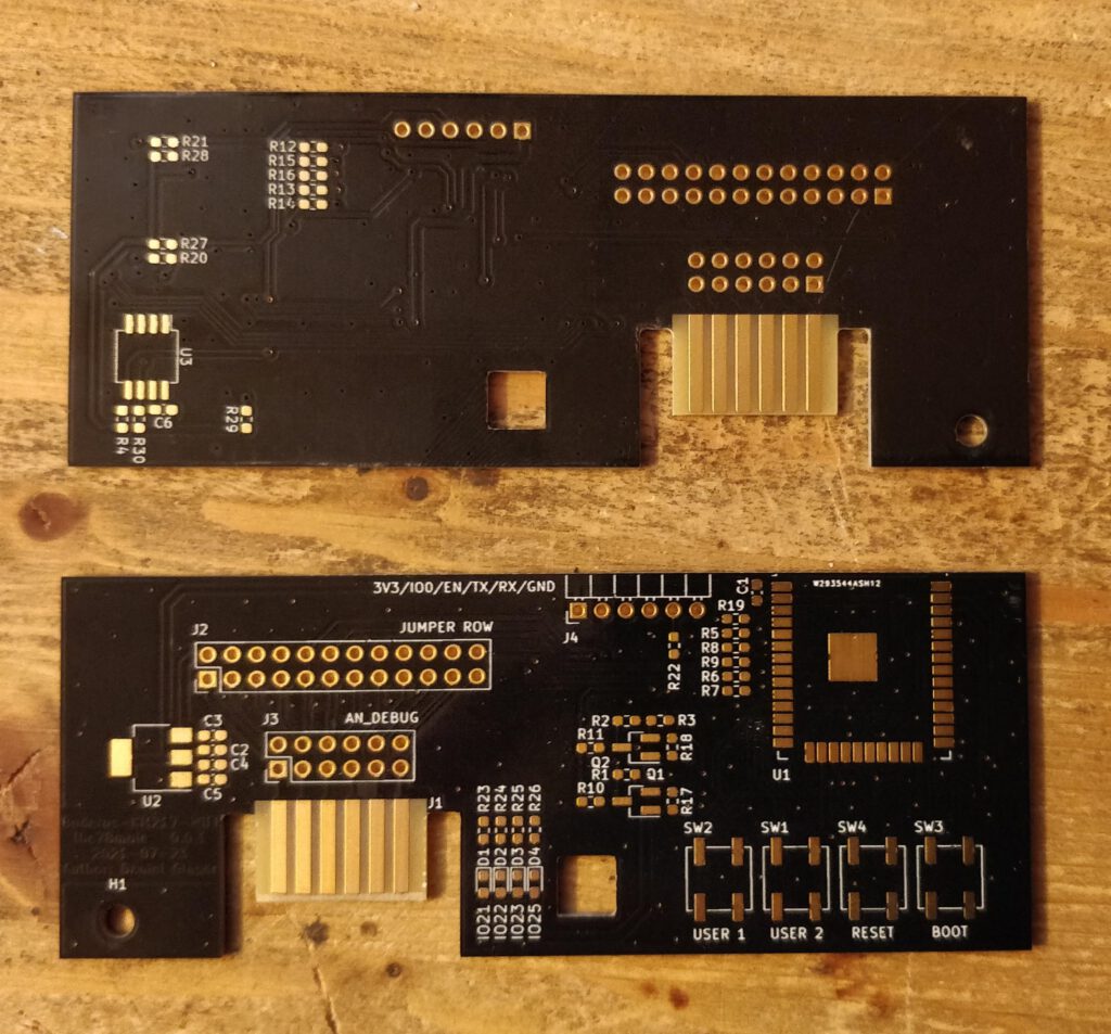
The PCBs look great and also the 0.3mm holes are totally in the center of the vias. There is no visible offset between any of the layers and I totally believe, that going down to 6 mil (0,15mm) with traces and spacings will be no problem.
I already rasped one of it to better slide into the socket. I’ll now prepare two boards to act as a wire extension using a flat ribbon cable between th AN_DEBUG (J3) headers and see, if I can measure the supply correctly and if I’m able to connect to the Buderus controller via TTL-UART. If this succeeds, I’ll populate the components of one card and start the implementation via ESPhome.
Important Bug-Fixes
Changelog V0.0.5
I took over all improvements, that have been suggested by Michael and ordered 50 assembled boards from PCBway. They will arrive end of November and can then be ordered on tindie or by sending me an email.
Changelog V0.0.4
Switched LM_RX and LM_TX since they have been swapped accidently.
Changelog V0.0.3
Buderus Communication Module Presence Detection
Buderus uses some module detection resistors (R1 and R2 on the original KM271) between the second and the fourth finger contact on the upper side. This relates to LM_P4 and LM_P8 in my schematic. The version with this patch is 0.0.3.
Changelog V0.0.2
One of the drawbacks of releasing stuff early is, that it often requires patches and fixes of hard- and software. Fortunately, most of them are easy to accomplish and my batch of first drafts is usually around 25 pieces for the early adopters that are experienced with hardware modifications (like me).
Mechanical
As you can remember, I took the measurments from images from the internet. I simply had no real hardware. And as murphy tells, the one side of the PCB is a little to long for the connector to slide in. So, the short edge beside the ESP-Module needs to be cut by one millimeter (I used a rasp). This should be done before soldering the components.

You should also sharpen the connector to make it easier to slide it into the receptor of your buderus control unit.
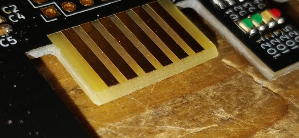
Power-Supply Issues
It seems, that the supply from buderus has quite some limits and maybe a relatively high impedance, so that if the ESP switches on WiFi, the supply drops down to a region, where the ESP resets or even worse, does not come up again a is trapped in a dead state until you reset manually or cycle the power. But this can be easily solved by two additional caps (100 uF/16V or more).
UART pinout
I somehow realized too late, that some of the external pins of the ESP32 module are used internally for important stuff like the program flash 🙁 So I need to remap them to unused pins and this requires some hardware patches. Fortunately, they are easy to accomplish. The new 0.0.2 in Gitlab already compensates for this issues.
PCB Assembly
Assembling a prototype should always be done step by step and intermediately checking, if everything still works. First, we should start with the ESP32-WROOM-Module (U1) and put the blocking capacitor (C1@100nF) into place. Then soldering the resistors need to connect to the programming interface (R19, R20, R12, R22). Their values do not matter too much. You can simply take something between 100 Ohms and 1 KOhm. It’s just to eventually compensate a 5V adapter and to protect a bit against overvoltages. Now you should solder J4 to connect the programmer.
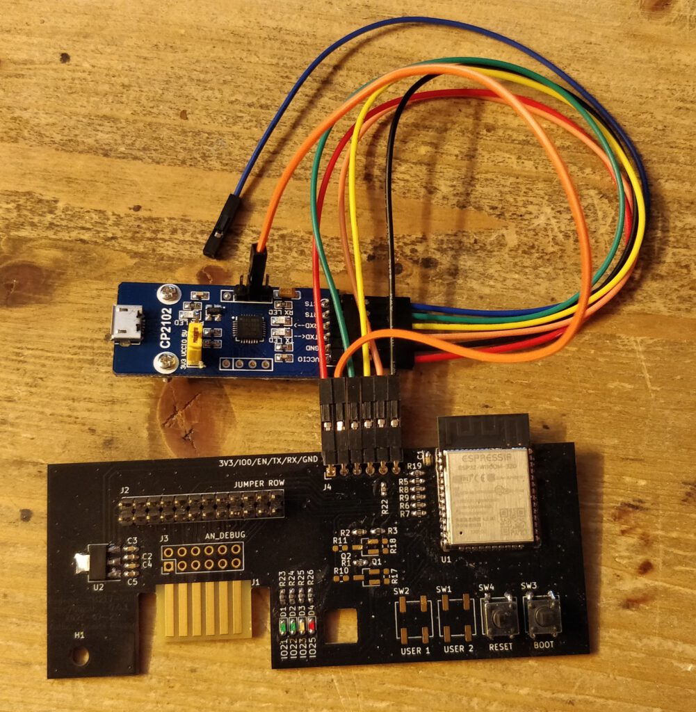
You should connect the supply, ESP32-RX to CP-TXD (orange1) and ESP32-TX to CP-RXD (yellow). Also CP-RTS should be connected to ESP-EN (green) and CP-DTR to ESP-IO0 (orange2). If you did this correctly, you do not need to place the RESET and the BOOT button since programming mode can then be entered correctly. Alternatively, only connect RX and TX as described, hold BOOT-Button down while shortly pressing the RESET-Button and then start to flash the module from your PC.
After wiring this, connect the USB to the converter, got to ESPhome and add a new target. Select ESP32 as the platform and if you are connected via HTTPS (e.g. with nabu casa) to ESPhome/Home Assistant, you can simply select to flash it locally using USB

If not connected with HTTPS, you can manually download the binary and then flash it e.g. using ESPhome flasher. After the first successful flashing, you can use wireless mode (OTA) to transfer new firmwares. Home Assistant will inform you, that a new device is available with the name given by you during create.
When this was successful, disconnect your PCB again and continue with assembly. I would suggest, to first put the LEDs (D1@green, D2@green, D3@yellow, D4@red) and their resistors (R23, R24, R25, R26) in place and edit your ESPhome device configuration to contain the following lines
switch:
  - platform: gpio
    name: LED1_Green
    pin:
      number: 21
      mode: OUTPUT
      inverted: true
  - platform: gpio
    name: LED2_Green
    pin:
      number: 22
      mode: OUTPUT
      inverted: true
  - platform: gpio
    name: LED3_Yellow
    pin:
      number: 23
      mode: OUTPUT
      inverted: true
  - platform: gpio
    name: LED4_Red
    pin:
      number: 25
      mode: OUTPUT
      inverted: true
After installing the new firmware, you should see four new switches in Home Assistant (maybe refresh the page). As soon as you switch one of them, the correlated LED will light up.
After succeeding with this, finish the assembly and put some jumpers on, to make the supply work. I first only jumpered the supply (two leftmost pins of J2), switched the buderus control off and put my module in place. Then I switched on again and checked, if I can still switch on the LEDs.
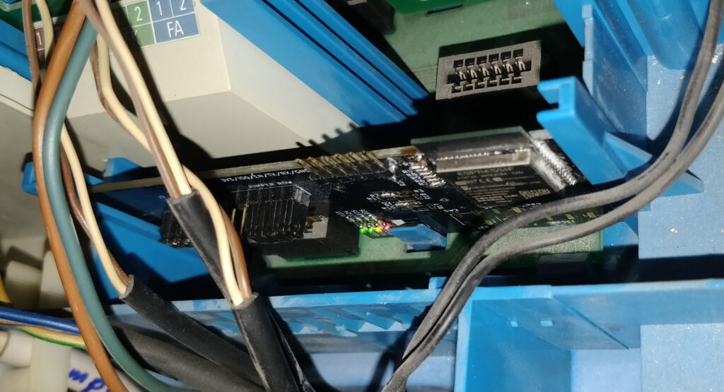
To get it out again, you need to release the little plastics lock at the bottom, that catches the rectangular hole in our PCB.

Putting On The Software Sauce
Home Assistant / ESPhome integration
The easiest way to integrate the heating controller into your smart home is by using Home Assistant and ESPhome, since there is now (2022-11-26) a working external component.

Check out my KM271-WiFi how-to page to get mor information on this.
How To Debug A remote Serial Connection Easily
Since the protocol of the buderus is not yet known very well to me and debugging all the stuff with ESPhome logs and quirks is a pain, I decided to forward and analyze the traffic on my PC.
See my blog post to get to know how to access serial data over ethernet on windows: The Remote Serial Debugging Nightmare

Unfortunately, I currently have no clue, what the group 0x04 represents…
The (not yet) Final Software
Since this will be a much harder task than designing just another ESP32 board, you need to wait some days (maybe weeks) for me to figure all that stuff out. I’ll need to send a control word on the serial connection to activate the reporting of the Buderus controller and then I also need to parse the data that is thrown out. I’m not yet excatly sure, how I’ll do it, but I plan to implement a new Sensor, that can be used also with a breadboard-type of electronics.
In the meanwhile, I received some help from Michael. He already connected some ATmega and a WiFi module to the original KM271 and implemented the reverse engineered protocol with help of some forum guys on mikrocontroller.net:
https://www.mikrocontroller.net/topic/309075
https://www.mikrocontroller.net/topic/141831
https://homematic-forum.de/forum/viewtopic.php?f=18&t=26955
Stay tuned, to keep updated…
You can get the design files in my project on GitLab (KiCad)…
Current State of Software
I just turned the inside out and decided, to create an external component, as it is the preffered way to do so, according to the ESPhome website.
To develop the component’s source, the easiest way is to install Visual Studio Code, install the ESP-IDF add-on and the C/C++ add-on within visual studio code. Then get the source of esphome via GIT, add it to your browse-path, enable samba share add-on on your Home Assistant, link the remote drive and start developing in VScode by opening the appropriate folder on the just linked share.
If you did so, you just need to create a folder on the share e.g. my_components, create another folder in it called „components“ and you can put one „local“ external component in there as one folder per component.

If you now add a config part to your ESPhome device YAML, you can easily adjust the source and instantly test it on your ESP.

In my case, the my_components folder is the root of the GIT repository, so I can simply push it to GitHub to get the most recent updates there. If I reach a certain state of my code, I’ll branch away from main to develop and only merge stable stuff back to main.
From the current sources you should get the Buderus monologue from the log:

# Param:'Identifier'
-------------------------
0x8000: 'Betriebswerte 1 HK1'
0x8001: 'Betriebswerte 2 HK1'
0x8002: 'Vorlaufsolltemperatur HK1'       (Grad)
0x8003: 'Vorlaufisttemperatur HK1'        (Grad)
0x8004: 'Raumsolltemperatur HK1'          (Grad)
0x8005: 'Raumisttemperatur HK1'           (Grad)
0x8006: 'Einschaltoptimierungszeit HK1'
0x8007: 'Ausschaltoptimierungszeit HK1'
0x8008: 'Pumpenleistung HK1'              (Grad)
0x8009: 'Mischerstellung HK1'             (Grad)
0x800a: 'nicht belegt'
0x800b: 'nicht belegt'
0x800c: 'Heizkennlinie HK1 bei + 10 Grad' (Grad)
0x800d: 'Heizkennlinie HK1 bei 0 Grad'    (Grad)
0x800e: 'Heizkennlinie HK1 bei - 10 Grad' (Grad)
0x800f: 'nicht belegt'
0x8010: 'nicht belegt'
0x8011: 'nicht belegt'
#
0x8112: 'Betriebswerte 1 HK2'
0x8113: 'Betriebswerte 1 HK2'
0x8114: 'Vorlaufsolltemperatur HK2'       (Grad)
0x8115: 'Vorlaufisttemperatur HK2'        (Grad)
0x8116: 'Raumsolltemperatur HK2'          (Grad)
0x8117: 'Raumisttemperatur HK2'           (Grad)
0x8118: 'Einschaltoptimierungszeit HK2'
0x8119: 'Ausschaltoptimierungszeit HK2'
0x811a: 'Pumpenleistung HK2'
0x811b: 'Mischerstellung HK2'
0x811c: 'nicht belegt'
0x811d: 'nicht belegt'
0x811e: 'Heizkennlinie HK2 bei + 10 Grad' (Grad)
0x811f: 'Heizkennlinie HK2 bei 0 Grad'    (Grad)
0x8120: 'Heizkennlinie HK2 bei - 10 Grad' (Grad)
0x8121: 'nicht belegt'
0x8122: 'nicht belegt'
0x8123: 'nicht belegt'
#
0x8424: 'Betriebswerte 1 WW'
0x8425: 'Betriebswerte 2 WW'
0x8426: 'Warmwassersolltemperatur'        (Grad)
0x8427: 'Warmwasseristtemperatur',        (Grad)
0x8428: 'Warmwasseroptimierungszeit'
0x8429: 'Ladepumpe'                       ['aus', 'Ladepumpe', 'Warmwasserpumpe', 'beide']
#
0x882a: 'Kesselvorlaufsolltemperatur'     (Grad)
0x882b: 'Kesselvorlaufisttemperatur'      (Grad)
0x882c: 'Brennereinschalttemperatur'      (Grad)
0x882d: 'Brennerausschalttemperatur'      (Grad)
0x882e: 'Kesselintegral 1'
0x882f: 'Kesselintegral 2'
0x8830: 'Kesselfehler'
0x8831: 'Kesselbetrieb'
0x8832: 'Brenneransteuerung'              ['aus', 'an']
0x8833: 'Abgastemperatur'                 (Grad)
0x8834: 'modulare Brenner Stellwert'
0x8835: 'nicht belegt'
0x8836: 'Brennerlaufzeit 1 Stunden 2'
0x8837: 'Brennerlaufzeit 1 Stunden 1'
0x8838: 'Brennerlaufzeit 1 Stunden 0'
0x8839: 'Brennerlaufzeit 2 Stunden 2'
0x883a: 'Brennerlaufzeit 2 Stunden 1'
0x883b: 'Brennerlaufzeit 2 Stunden 0'
#
0x893c: 'Aussentemperatur'                (Grad)
0x893d: 'gedaempfte Aussentemperatur'     (Grad)
0x893e: 'Versionsnummer VK'
0x893f: 'Versionsnummer NK'
0x8940: 'Modulkennung'
0x8941: 'nicht belegt'
It is already possible to read and set most of the parameters of the Buderus control unit. To my knowledge, the only pieces left are the time setting of the buderus and configuring the heating programs. But since I do hot water completely with my Home Assistant using automations, calendar entries and the WW On/Off paramter, I have no need to do this remotely.
Have fun!
Some other references
- Hirnfasching Blog (german)
- 3964R Protocol (Wikipedia german)
- sjs-77-logamatic (GitHub german)
- Steuerzeichen (de), Control Characters (en)
Stromversorgung ?!
Hallo,
ich hab seit ein paar Wochen das Modul in der Heizung und bin eigentlich begeistert nur gestern ist was „komisches“ passiert… Ich hab an der „EDV“ gebastelt und der WLan AP für das Modul war ca.1h weg… irgendwann ist dann bei 28°C Außentemperatur der Brenner angesprungen. Grund dafür gabs eigentlich keinen.
Mir ist dann aufgefallen das das LCD Display der Heizungssteuerung „stufenweise“ Kontrast verliert wenn das Km271 Modul kein WLAN findet?!? –> siehe Video: https://www.youtube.com/shorts/hDZSB68njl4
Sieht aus wie „Stromversorgung bricht zusammen“ und scheinbar hat das dann irgendwie zu dem Brennerstart geführt?!
Gibts ne Möglichkeit irgendwo die Versorgungsspannung abzugreifen um das zu prüfen?
Antwort von MolesBlog
Die etwas schwachbrüstige Spannungsversorgung der Buderus-Steuerung ist ein bekanntes Problem. Einige wenige Steuerungen (ich schätze 5%) scheinen da besonders betroffen von zu sein, die meisten garnicht.
Direkt am Senosr-Header Pins 1, 3, 5, 7 bieten sich an. Die Belegung steht auch auf der Unterseite des Moduls.
Man kann natürlich die Spannungsversorgung abgreifen.
Besser wäre das Thema in den GitHub-Discussions zum Modul aufgehoben 😉
Frage Einbau
Moin Daniel,
Erstmal danke fuer deine ganze Arbeit. Hast du irgendwo ein Bild wie oder wo genau man die Platine einbaut. Ich komme aus der Softwareecke, und wer aus der Anleitung von Buderus nicht ganz schlau. Ich konnte die Platine leicht nicht „einfach“ einstecken.
MfG
Thomas
Antwort von MolesBlog
Gibt eigentlich nur einen Steckplatz, wo sie schön reinpasst…
Fragen
Hi!
Ich habe das Modul jetzt schon länger im Einsatz und es funktioniert soweit super!
Nur zwei Dinge… Wenn bei mir mal das WLAN abstürzt, verbindet sich das Modul anscheinend nicht selbstständig wieder mit meinem Router. Ist das bekannt?
Ich gehe dann immer hin und mach die Heizung einmal aus/an. Dann geht wieder alles…
Und das umstellen der Gewünschten Warmwasser Temperatur funktioniert irgendwie nicht. Ist bei mir jetzt aber weniger relevant. Hab einen festen Wert genommen und das reicht mir auch 🙂 – Aber wenn man sich bspw. eine Legionellen Schaltung bauen wollen würde, gäbs evtl. Probleme.
Danke!!
Antwort von MolesBlog
Hallo Dustin,
bei mir (mit ESPhome) funktioniert beides (WiFi-Reconnect und Warmwasser) hervorragend. Meine Warmwasser-Solltemperatur wird ständig umgestellt, weil mein Ölbrenner nur als Aushilfe für die Wärmepumpe arbeitet und ich dass alleine über Warmwasser regele.
Zudem ist mir nichts bekannt von solchen Problemen.
Welche Firmware nutzt Du denn überhaupt? Dewennis oder ESPhome?
Beste Grüße,
Daniel
Neue Lieferung?
Hallo Daniel,
sehr cooles Projekt. Kannst du abschätzen, wann es wieder bestellbar ist?
VG
Sebastian
Antwort von MolesBlog
Hallo Sebastian,
neue Lieferung ist in der Mache. Ich kann aktuell schwer einschätzen, wie lange es dauert. Demnächst ist in China wieder ein Feiertags-Block und wie gut das dann am Ende mit der Bauteilbeschaffung, Zoll und Co klappt, weiß man vorher leider auch nicht. Realistisch dürfte Mitte Februar sein…
Grüße,
Daniel
Tolle Leistung
Moin,
das ist ja echt irre, was hier erreicht wurde! Besser als die originale vom Hersteller! Ich bin in den letzten Jahren immer mal wieder versucht für meine Heizung was zu bauen, das Problem ist die HW4201 Steuerung. Ich finde nicht welchen Protokoll-Dialekt die FMEC-Fernbedienung spricht und ob man nicht lieber an den ECO-CAN gehen sollte. Hat hier jemand schon mal eine Lösung gesehen? Danke für eure Hilfe,
Sebastian
Antwort von MolesBlog
Hallo Sebastian,
Da kenne ich mich leider nicht aus… Lieber mal ins Mikrocontroller- oder Haustechnik-Dialog-Forum posten…
Grüße,
Daniel

3 Kommentare