As a mole, you sometimes have the same problems like humans: Nasty neighbours. In my case, mice. I have a cat named Tommy (his full name is Thomas Alva Edison G.) and he takes it’s job quite seriously. He catches around 1.5-2 mice a day (or better say night?). Most of them are headless. Dear IT guys, mice don’t tend to have screens, but headless here means, without a head. Unfortunately, some of them seem to be better suited as a toy and kept alive. These little animals are really smart and quickly hide behind a cabinet or somewhere else when not continously watched. After half an hour, Tommy loses interest, these mice found a new home and tend to stay.
Building a Smart Mouse Trap
Everybody knowing me will correctly guess, that I didn’t simply bought a trap. And as it was saturday late evening, when I decided to hunt them down, I started printing one. You can find a nice one on printables here. The print took a few hours and was finished, just before I went to bed. So I placed it in the basement, where I definitely had a mouse. And I forgot about it until Tuesday. When I came back to the trap, you didn’t even need to look, you could smell it already, that the mouse did not piss off, but it pissed. I put it in the garden for Tommy to hunt it again 😛 and cleaned up the mess in the trap with a huge amount of water.
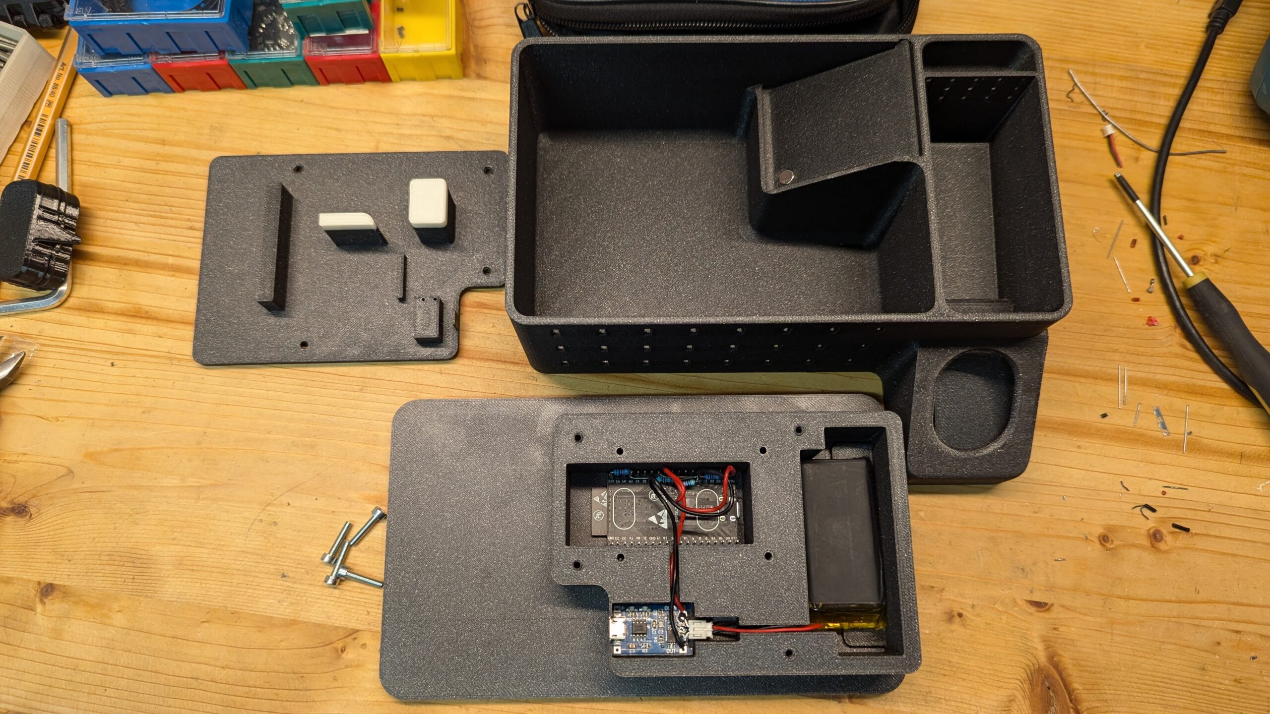
That was the point, where I thought about a trap with notification. So I took the 3D model and modified it first, to place a 6×3 magnet in the flap and added an opening in the lid at the right place to add some electronics stuff for detection of the magnet and sending the information to my smart home, where I can do whatever I want with that data (e.g. send a pushover message).
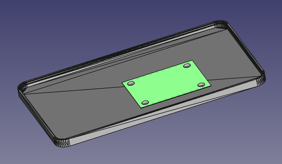
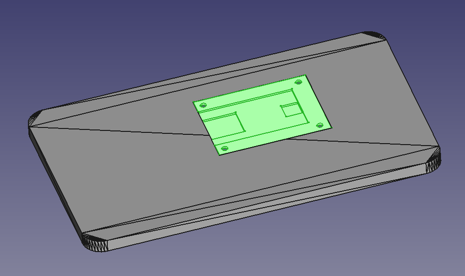
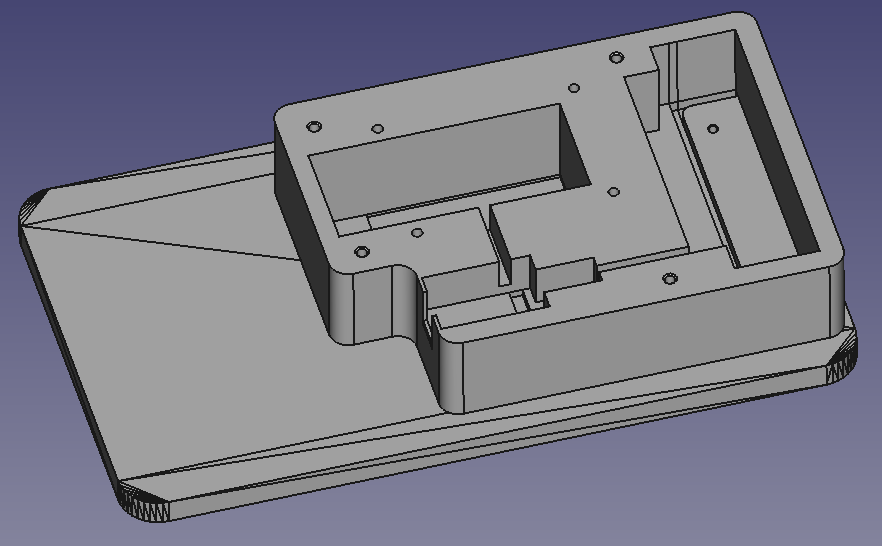
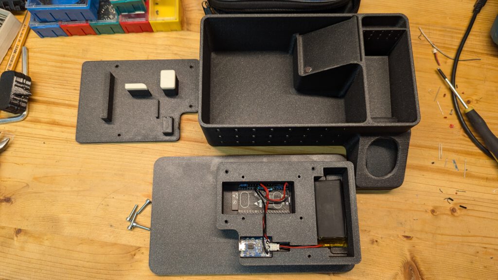
As a sensor, I decided to use the integrated magnetic field sensor of the ESP32 (the old one, newer ones don’t have it integrated anymore). Additionally, I took a simple TP4056 USB-Li-Ion-Charger module from AliExpress and a LiPo battery, I just had lying around. But the case is designed that it can receive a 18650 cell (optional including a battery holder).
Charging looks like this:
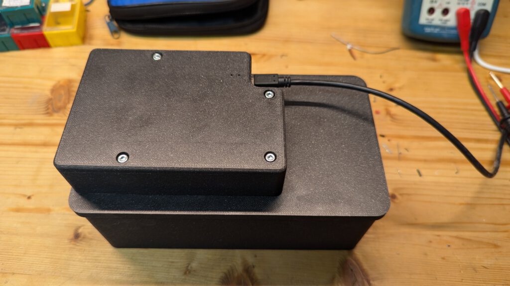
The charger state can be observed through the tiny through-holes directly above the chargers LEDs. Red means charging, blue means „full“.
You can find the model files (including my changes) on Printables.
The Firmware Trap – or the Trap Firmware ???
To test it in action, I decided to use ESPhome, since it has the magnetic field sensor well integrated. After a successful test I’ll implement a BThome firmware, to extend battery life by magnitudes, but for now, it is the perfect rapid prototyping solution.
ESPHome + Home Assistant Integration
The ESPhome YAML looks as follows:
esphome:
  name: mousetrap1

esp32:
  board: esp32dev
  framework:
    type: arduino

logger:

# Enable Home Assistant API
api:

ota:
  - platform: esphome
    password: <XXX>

wifi:
  ssid: !secret wifi_ssid
  password: !secret wifi_password

  manual_ip:
    static_ip: 172.22.3.233
    gateway: 172.22.0.1
    subnet: 255.255.240.0

sensor:
  - platform: esp32_hall
    name: "Mouse Trap 1 Magnetic Field"
    id: mouse_trap_1_mag
    update_interval: 1s
  - platform: adc
    name: "Mouse Trap 1 3V3"
    id: mouse_trap_1_3v3
    pin: 39
    attenuation: auto
    update_interval: 10s
    filters:
      multiply: 3.128   # 100K/47K divider
  - platform: adc
    name: "Mouse Trap 1 VBat"
    id: mouse_trap_1_vbat
    pin: 33
    attenuation: auto
    update_interval: 10s
    filters:
      multiply: 3.128   # 100K/47K divider
To monitor the battery and supply voltages, I added a 100K/47K resistor divider. These two dividers will draw around 0.02 mA (less than 100 mW) each, which is quite fine. The ESP32 will draw not much less even with Bluetooth LE only, because it needs to sample the magnetic sensor quite often (at least once per second) to detect the quick flap movement by a mouse. With WiFi enabled, it takes around 100 mA and the battery will only last for one day.
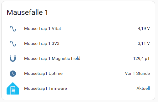
For the quick test with ESPhome and Home Assistant, this looked like this:
And with an automation and the Pushover service, my smartphone’s notification shows as follows:
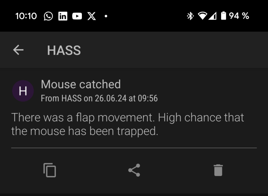
To test it, I just turned the trap over and within only a few seconds, my Smartphone received the notification.
Since I already have some bluetooth proxies around my house, next step is, to write a BThome compliant firmware to send the notification…
BTHome Firmware using ESP32 ULP
When trying to implement it, I quickly git screwed up by the fact, that Espressif purged any evidence of the hall sensor in their first ESP32 from all current datasheets and also from their ESP-IDF 5.x.x. So it was really a hard way, to put all pieces together…
The ULP – The Ultra Low Power Coprocessor
Another complicated task was the ESP32’s ULP, the Ultra Low Power coprocessor, sometimes referred as the FSM (Finite State Machine). In recent ESP32s, they upgraded the FSM by a small RISC-V core, which makes information retrieval not an easier task. And imagine, it get’s again a bit more complicated, if you need to chose between Arduino and ESP-IDF. Long time ago, I decided to always use platform.io, because it gives the choice to use both of them, simply by selecting the framework during project initialization. Unfortunately, many examples don’t use platform.io. Importing it sometimes is smooth, sometimes a bit more tricky… Because of the better ULP support, I decided to go with ESP-IDF. In Arduino, you could use the ulptool, using C-Macros or the assembler instructions of the ULP directly. In ESP-IDF, you can directly write these ULP assembly nor relying on a 3rd party tool and it is documented a bit better (here and here). Since there are only a handful (25 + 1) of different instructions, it is easy to learn, but since your programming power with ULP assembly is really limited (or better say low level), the progress is really slow. What is a simple if-then-statement in C, can get a cruel group of instructions in ULP-assembly, mostly, because the comparision is complicated and limited on the equal and overflow flag and the else is implemented around one’s elbow to get to its thumb. Form your own opinion :-):
	/* Get the stored value from first phase */
	move r3, hallphase0d
	ld r1, r3, 0
	/* Subtract it */
	sub r0, r1, r0

	/* Get the offset and subtract it */
	move r3, halloff
	ld r2, r3, 0
	sub r0, r0, r2 /* 99 */

	/* If result crossed 0, decrease offset
	   by one, otherwise increase */
	jump saveoff, eq
	jump offs_dec, ov
	add r2, r2, 2

offs_dec:
	sub r2, r2, 1

saveoff:
	st r2, r3, 0
Honestly, there are other jump instructions, where you can use less-than, less-equal, equal, greater-than,…, but they need even more assembly instructions and (most important) often need variable and register space. If you only have four registers and retrieving or storing a variable needs a register to hold the address and another for the data, this piles up really quickly. Using flags is way easier with the downside of limited (two) comparision types.
Also the error messages of the ULP assembler are not worth to be printed. The line numbers in the error output do not align with your assembly file and the message itself gives no hint on what you did wrong. Sometimes, it is just that you forget the obligatory , 0 after a load or store instruction (this was the case in the above example, I forgot the , 0 in the line before the one with the /* 99 */ comment an the assembler mentioned an error in line 99, but in my IDE, the line with /* 99 */ is line 191.
Trying out many, many different examples (simple GPIO, hall sensor, adc, many other examples) using the ULP for ADC readings, hall sensor reading and the processing of the data and endless loops of build-flash-test-loops, I finally digged the tunnel and not ended at a concrete wall… You can find the complete code in my GitHub repository.
Comparision ESPhome WiFi vs. BTHome ESP-IDF + ULP
As expected, the BTHome ESP-IDF ULP implementation consumes much less power than the ESPhome solution. Not only switching from WiFi to Bluetooth, but als entering the Deep Sleep mode and only running the ULP increased the runtime of the Trap from around 10 hours to multiple days.
Explanations and Improvements
Battery Life
I guess, when I remove the power LED from the DevKit, I could extend it to more than a week. An additional improvement would be, to design the whole electronics myself, since the DevKitC is not the most efficient solution. The USB-UART consumes power and also the LDO seems not to be a low quiescent type.
Also the usable voltage range of the battery can be extended. Beside the possibly high IQ, the LDO needs a decent amount of voltage drop, to function properly, resulting in a ESP32 brown out at around 3.6V battery voltage. But there is plenty of room down to 2.3V (lowest ESP32 voltage) or 2.5V (the limit for LiPo) that is not used with the ESP32-DevKitC. To use the full range, someone could integrate a Buck-Boost converter (e.g. ISL9122A or TPS63020) that converts almost everything into a stable 3.3V supply.
Additionally, sending BThome packages could be eventually skipped most of the time, when there is no real event to be published. But for further debugging purposes, I’ll keep it at this rate.
Reduce False Alarms
Since the hall sensor creates a huge amount of noise, filtering it somehow is mandatory. Also using both phases of the hall sensor circuitry is mandatory. Only relying on one phase will just not work. The drift is immense and the supply rejection is very poor.

The hall sensor provides two so-called phases, each driving almost the same current through the hall element, but in different directions. This leads to the opposite voltage UH on the measurement contacts. Another drawback of the ESP32 hall sensor is, that the voltage is not measured differentially. Instead, two channels of the ADC are used, resulting in an even worse measurement. So in total, you need to compensate with a decent avaraging of the measured voltages for both phases. Implementing this in ULP is not a really trivial task.
The resulting measurment process can be described as this:
- initialize hall sensor with phase 0
- get ADC1 Channel 0 (VP) reading –> add to R1
- get ADC1 Channel 3 (VN) reading –> add to R2
- get back to step 2 (22 = 4 times)
- divide R1 and R2 by 4 –> mean value
- save the value
- switch to phase 1
- get ADC1 Channel 0 (VP) reading –> add to R1
- get ADC1 Channel 3 (VN) reading –> add to R2
- get back to step 8 (22 = 4 times)
- divide R1 and R2 by 4 –> mean value
- subtract the stored phase 0 value from the phase 1 value
- store the raw hall value
To compensate for long and mid term drift, I implemented the offset to follow the raw hall value. Every time, the computed hall value (which should be 0 for the „silent“ case) differs from 0, the offset is increased or decreased by one. This way, it follows the drift quite quickly. But from time to time (about every few hours), the hall sensor creates a spike even with all the averaging and filtering applied. Therefore, there should be a suppression of a single event in the sourrounding C-code. This is quite an easy task, only adding another variable stored in the RTC slow memory, which is retained during deep sleep.
If the sensor generates a value outside the theshold range, it will set a flag and wake the ESP immediately to process the data and send a BThome message. If there is no detection for 200 times, it will wake the ESP but not set the flag to send the data as a keep alive signal (and including curent voltage and the unchanged event count).
To understand this spike better, the BThome data should be temporarily extended by the raw hall values (both phases, both voltages). But I do not yet understand, how this needs to be implemented correctly. The current BThome data packet is already at it’s size limit and the packet needs to be split in multiple transmissions. Maybe it can be rotated through, sending the flap event and the count, then sending voltage reading, then sending raw values and in case of an event, prioritize the event packet. Sending each packet every time will waste a lot of energy, because you need to wait 1.5 seconds after initiating the transfer to be sure, the data got out of the ESP32.
Conclusion
To get rid of all the problems with the ESP32 hall sensor and be able to use more modern and lower energy ESPs or even another chip (like the nRF BLE from nordic), someone could switch to an external hall sensor or even a reed contact. If I feel the need, I’ll also implement this and write another article about it.
For the time being, the trap serves well, but I ran out of peanut butter (the most effective bait). And since it traps mice mostly within a single night, the false alarms are not too annoying. Most important is, that I get a reminder on the armed trap, not to forget freeing the trapped. This way, I solved the toilet-smell problem in my underground domicile and I’m a happy cat owning mole again… Unfortunately, it does not solve another problem with my cat. Bringing other animals home, that don’t need „trap treatment“. So I already need to remove: a headless squireel (did obviouly not fit through the cat flap with head attached) 😢, two birds 😒 and, by far most annoying, little moles from time to time 😭 (no relatives until now). nature is cruel, so cats are… The upside of having a cat is, that we got completely rid of marten, that granted us sleepless nights, raising their babies in our roof, directly above our sleeping room.
Hope this was intersting for you, you enjoyed reading and you gained another digger superpower 🙂
Schreibe einen Kommentar