OK, guys, as you may have noticed when reading my post about my new heating system, I have three heat meters installed that have M-Bus connectivity. I also wrote some posts about M-Bus and how to push the data with MQTT, reading M-Bus devices in general or a more basic M-Bus post…
OK, I just realized, that I’m using a bus that I personally don’t favour, way to much…
So, Why the F*** again M-bus? Because I did not yet manage to implement my BLE-Module for this type of heat meters. The Bluetooth-Module will also speak some sort of M-Bus-protocol internally with the main meter microcontroller, so I ordered the M-Bus variant to have it correctly parametrized in the very beginning. And to be honest, I did NOT rip an opto-head from my previous employer to do the parametrization.
The hardware part of the BLE-Metering-Module is already finished (and will soon become open source), but without a working software, this is just useless. So I decided to give the M-Bus a try with node red and write some post about it.
The Hardware
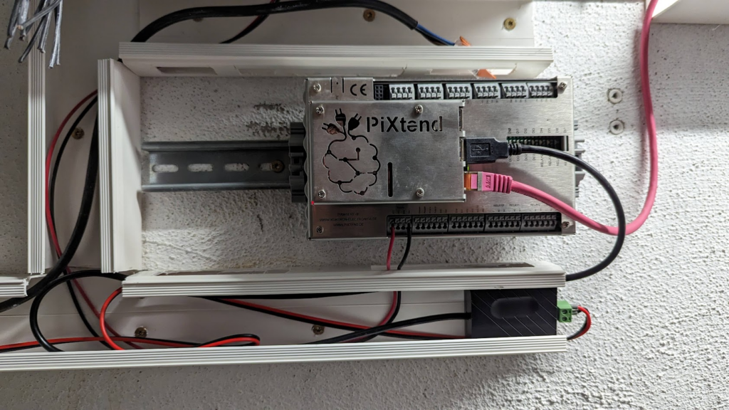
OK, first things first. The hardware I’m using is a PiXtend controller, but every other Pi, Pi Clone, PC, Server, Data Center,.. will do, if there is some USB port (or serial port with another adapter) available. I got my USB-M-Bus-Adapter from aliexpress. I then wired the remainder of my installation. I had most of the cables already running in ducts and only need to screw the wire into the terminals of the adapter.

This is my PiXtend V2 -S-, some little Pi-based PLC controller, running node red. I completely refuse to use CODESYS, even if I did some PLC programming in my younger days. This stuff is even to dirty for moles (I hate closed source) 😛

On the left, you can see the Landis+Gyr Ultraheat T230 (technical description, user manual) with a composite flow tube Qp=1,5 m³/h and an M-Bus module installed. The four wires on the bottom are (from left to right) flow measurment sensors, return temperature sensor, forward temperature sensor and the M-Bus cable. On the right side, you can see a heating water pump Grundfos Alpha 3, that has bluetooth integrated. From this pump I hope to get some flow, pressure and electical values (stay tuned to read about it).
The Software Part
Getting Your Device Right
Back to the tindering stuff… After connecting the USB-M-Bus-Adapter, dmesg showed it was found and attached as /dev/ttyUSB0:
pi@pixtendheat:~ $ dmesg | tail -n 13
[288894.133665] usb 1-1.1.3: new full-speed USB device number 5 using dwc_otg
[288894.265188] usb 1-1.1.3: New USB device found, idVendor=0403, idProduct=6001, bcdDevice= 6.00
[288894.265214] usb 1-1.1.3: New USB device strings: Mfr=1, Product=2, SerialNumber=3
[288894.265225] usb 1-1.1.3: Product: FT232R USB UART
[288894.265235] usb 1-1.1.3: Manufacturer: FTDI
[288894.265244] usb 1-1.1.3: SerialNumber: AQ02CG2X
[288894.318118] usbcore: registered new interface driver usbserial_generic
[288894.318184] usbserial: USB Serial support registered for generic
[288894.330775] usbcore: registered new interface driver ftdi_sio
[288894.330840] usbserial: USB Serial support registered for FTDI USB Serial Device
[288894.331041] ftdi_sio 1-1.1.3:1.0: FTDI USB Serial Device converter detected
[288894.331171] usb 1-1.1.3: Detected FT232RL
[288894.335084] usb 1-1.1.3: FTDI USB Serial Device converter now attached to ttyUSB0
To make life easier, especially when connecting other USB-serial adapters (which I will certainly do in future for connecting ModBus devices) there is a chance, that device names will swap one time. Also when replacing an adapter, you would need to change all your software settings. Therefore, I got used to fix the names of such devices and make them easily customizable using udev.
For this, you need to create a udev rules file. Take the serial from above output, in my case AQ02CG2X and run:
pi@pixtendheat:~# udevadm info --name=/dev/ttyUSB0 --attribute-walk | grep AQ02CG2X
    ATTRS{serial}=="AQ02CG2X"
Now create a new udev rule with this pieces to symlink a new device /dev/usb-mbus. You can also use vi to create/edit the file 🙂
pi@pixtendheat:~# echo SUBSYSTEM=="tty", ATTRS{serial}=="AQ02CG2X", SYMLINK+="usb-mbus" | sudo tea /etc/udev/rules.d/50-usb-tty-mbus.rules…refreshing udev…
sudo udevadm triggerIf you now list the contens of /dev, you will see a symlink usb-mbus pointing to ttyUSB0. This will happen always automatically, when plugging in this specific USB device. If you need to replace it, just find the serial number again with dmesg (after plugging in) and replace it in your udev rule.
Powering Up Node-Red
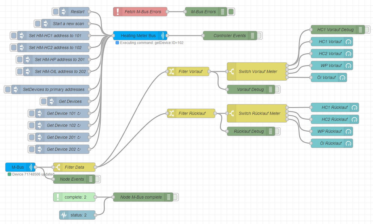
If everything was OK, let’s pull it into node-red. The description of the module I’m using is called node-red-contrib-m-bus. After installing this module to the palette, you need to restart your node-red. On my PiXtend this is easily achieved by issuing the command systemctl restart nodered.service on the shell.
All you get for your efforts are two lousy new nodes:

And just a remark from my side, the M-Bus module needs some improvements… Maybe I’ll contribute to it in the near future. It needs a command that processes the list of devices and reads their values without scanning for secondary addresses…
To get anything from the meter, you first need to find it on the bus. If you only have one meter connected, chances are high, that is has the default address 1 or simply responds to broadcasts. „Unfortunately“, in my case there are four meters conected and more will follow with every upgrade of the heating circuits.
The settings of the controller node are quite easy. Place the controller node in your flow, double-click it and click on the pencil icon in the properties view, then add a new client:

When saved, the resulting main properties view of the control node should look like this:

As soon as you deploy your program, the nodes will show scanning. Be patient, this can take a minute or two. M-Bus is not known for ultra-fast scanning and data transmission.

The reward for all this efforts is a simple line of log 🙂

The second node will now start to emit (many) messages with data from each meter. It will continuously retrieve this from the meters as long as you have „Auto scan and read“ enabled in the client of the controller node. Following is only a tiny fraction of the data from the first meter in the list:

[…]


There are many more values, like the min and max temperatures for flow and return, flow rate maximum value,… Everything you would like to know from the meter 🙂
Optimizing Communication
Since MID heat meters need to be calibrated (or exchanged) every five years, there is a good chance, that secondary addresses will change sooner or later. Therefore, it is a good practice, to assign a primary address to each meter and use this for communication. When you then need to exchange the meter with a new one, you can simply assign the same primary address as the old meter had before. Your whole software then needs no change at all, only sending the „setPrimary“ command, containing the following data and you can simply use an inject node to craft the message:

The whole content of the payload field is as follows:

Then connect the inject node to the controller node, deploy your flow and press the inject button.


Now, you only need to do this for all your meters and use the setDevices command to hand over an array of meters that should be updated in the auto scan and read loop (this was a default setting in your controllers client config). Therefore, create another inject node, generating the appropriate command.


The resulting message from the controller was:

Now everything should be a bit faster and way better for maintenance 🙂
Improving The Flow
Coming soon…
Getting The Values into Home Assistant (or on MQTT)
Coming soon…

Schreibe einen Kommentar