Attention!!! 0.0.6 changed some of the pins and is not 100% compatible anymore. Please keep in mind, when using the ESPhome YAML or when implementing your own firmware.

If you need to assemble a few parts (ECAPs and optional stuff) or flash another firmware, watch my video on YouTube.
Introduction
At first, do not get confused, KM217 and KM271 ist the same, I just had a number swap in and it is simply impossible to change all the historic stuff and naming 🙁
If you ordered the module described in Reverse Engineering the Buderus KM271 – And Making It WiFi-Flying on ESPhome and Home Assistant from my Tindie store or built it on your own, this is the place to search for, when it comes to getting it up and running. You will find the Information for both versions (0.0.5 and 0.0.6 here). Version 0.0.6 is already available and can be ordered.
Known compatible Heating Control Units
- Buderus Logamatic 2107 M (this is my own unit)
- Logamatic HS2102 (not EcoMatic !!!)
If you have one of my boards and a different control unit that works, please tell me about, so I can add it to this list 🙂 If you are not 100% sure, I have still plenty of old bare 0.0.5-Boards for a very low price. Antoher option is to print one of the PCB pages with 1:1 scale, glue it on a cardboard cut it out and test if it fits in your heating controller.
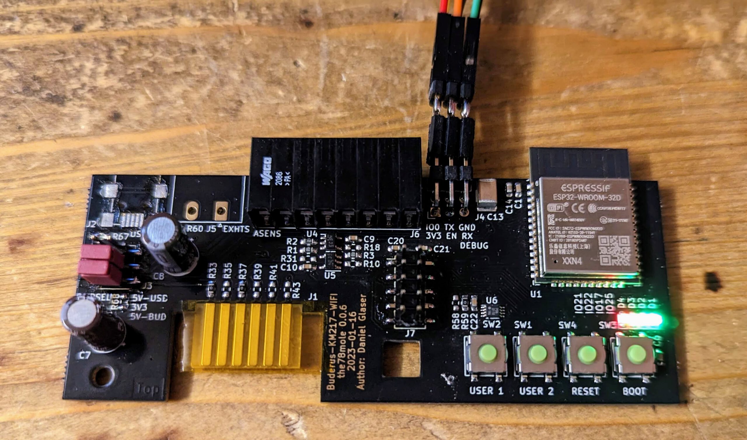
The Hardware
To make your life easier for aseembly and to find the parts and signals, here is the interactie BOM.
The Software
There is a ton of software alternatives for the board, but I’ll only describe three of them in more detail. You can select the firmware when you order the board.
Default, no FW selected: Blinkenlights
At first, I’ll just tell you, what is on the board, when you did not select any firmware during your order on Tindie. It is a simple test program, that ensures, that the ESP32 and the LEDs are working.
It does nothing more than rolling through the 4 LEDs on the board.
It will be possibly extended in future to catch hardware and assembly bugs, should they arise in future.
You can find it on GitLab. Use VSCode with PlatformIO to open, compile and flash it. This is also a very nice foundation for developing your own firmware.
Flashing can be done, by connecting power, ground, RX and TX. IO0 and EN is not needed and can be triggered with the buttons. Press BOOT and keep it pressed, shortly press RESET and start your flash tool. Then release BOOT and flashing will start.
I’ll possibly improve the Blinkenlight to be able to update the board via WiFi or BLE. If you feel responsible to do this, I would be happy to take the pull request. If I get a working firmware, the minimal thing I would do is refunding the board you bought from me 🙂
Sven’s great MQTT-firmware
Sven published a firmware on GitHub for my module that speaks MQTT on the network. This was probably the most complete piece of code for my module before JEns accepted the challenge on the ESPhome part. The „only thing“ you need to do is installing VSCode and the PlatformIO addon, set the credentials for WiFi, MQTT and OTA (in include/Credentials.h), compile and flash it to the board.
ESPhome
If you selected ESPhome, you will get an (older) ESPhome firmware version for this board. But as you will update the firmware after adjusting the config, you will have the latest firmware aligned with your ESPhome instance. Currently, the firmware is likely to be feature complete and runs without problems. See the section below, ho to connect to your board.
Diggers Full Example YAML (Drop Down Accordeon)
esphome:
  name: buderus-km217
  platform: ESP32
  board: esp32dev

# Enable logging
logger:

# Enable Home Assistant API
api:

ota:
  password: "XYZ"

wifi:
  ssid: !secret wifi_ssid
  password: !secret wifi_pass

  # Enable fallback hotspot (captive portal) in case wifi connection fails
  ap:
    ssid: "Fallback Hotspot"
    password: "XXX"

captive_portal:

uart:
  id: uart_bus
  tx_pin: GPIO2
  rx_pin: GPIO4
  baud_rate: 2400

external_components:
#  - source:
#      type: local
#      path: my_components/components
#    components: [ km271_wifi ]
  - source: github://the78mole/esphome_components@main
    components: [ km271_wifi ]


km271_wifi:
  - id: budoil
    uart_id: uart_bus

# SPI starting from version 0.0.6
spi:
  clk_pin: GPIO18
  mosi_pin: GPIO23
  miso_pin: GPIO19
  id: bus_spi1

# nCS for SPI is GPIO15

i2c:
  sda: GPIO13
  scl: GPIO16
  scan: true
  id: bus_i2c1

# For version 0.0.6
# For triggered actions, I2C devices can use GPIO14
# To enable the I2C level shifter (I2C_EXT_EN), use GPIO 12

status_led:
  id: ledgn1
  pin:
    number: GPIO21
    inverted: true

number:
  - platform: km271_wifi
    warm_water_temperature:
      name: "Warmwassersolltemperatur Tag"

select:
  - platform: template
    name: "Warmwasser Betriebsart"
    id: warmwasser_betriebsart
    entity_category: config
    optimistic: true
    options:
      - Dauerhaft aus (0)
      - Dauerhaft ein (1)
      - Automatik (2)
    initial_option: Automatik (2)
    set_action:
      - lambda:
          auto index = id(warmwasser_betriebsart).index_of(x);
          if (index.has_value()) {
            uint8_t command[] = {0x0C, 0x0E, (uint8_t)index.value(), 0x65, 0x65, 0x65, 0x65, 0x65};
            budoil->writer.enqueueTelegram(command, 8);
          }

binary_sensor:
  - platform: km271_wifi
    boiler_error:
      name: "KM271 Kesselfehler"
    boiler_running:
      name: "KM271 Kesselbetrieb"
    load_pump_running:
      name: "KM271 Ladepumpe"

sensor:
  - platform: km271_wifi
    heating_circuit_1_flow_target_temperature:
      name: "KM271 Vorlaufsolltemperatur"
    heating_circuit_1_flow_temperature:
      name: "KM271 Vorlauftemperatur"
    hot_water_target_temperature:
      name: "KM271 Warmwassersolltemperatur"
    hot_water_temperature:
      name: "KM271 Warmwassertemperatur"
    boiler_target_temperature:
      name: "KM271 Kesselvorlaufsolltemperatur"
    boiler_temperature:
      name: "KM271 Kesselvorlauftemperatur"
    outdoor_temperature:
      name: "KM271 Außentemperatur"
    heating_circuit_1_room_target_temperature:
      name: "KM271 Raumsolltemperatur"
    heating_circuit_1_curve_n10:
      name: "KM271 Heizkurve -10 °C"
    heating_circuit_1_curve_0:
      name: "KM271 Heizkurve 0 °C"
    heating_circuit_1_curve_p10:
      name: "KM271 Heizkurve +10 °C"
    boiler_turn_on_temperature:
      name: "KM271 Brennereinschalttemperatur"
    boiler_turn_off_temperature:
      name: "KM271 Brennerausschalttemperatur"

  - platform: wifi_signal
    name: "KM217 WiFi Signal Sensor"
    update_interval: 60s

  - platform: adc
    pin: 36
    unit_of_measurement: "V"
    name: "KM217 5V Supply"
    accuracy_decimals: 2
    update_interval: 5s
    attenuation: 6dB
    filters:
      - multiply: 27.7317
      - throttle_average: 60s

switch:
  - platform: gpio
    name: LED2_Green
    pin:
      number: 22
      mode: OUTPUT
      inverted: true
  - platform: gpio
    name: LED3_Yellow
    pin:
      number: 17
#     number: 23  # For 0.0.5
      mode: OUTPUT
      inverted: true
  - platform: gpio
    name: LED4_Red
    pin:
      number: 25
      mode: OUTPUT
      inverted: true
Connecting to the board
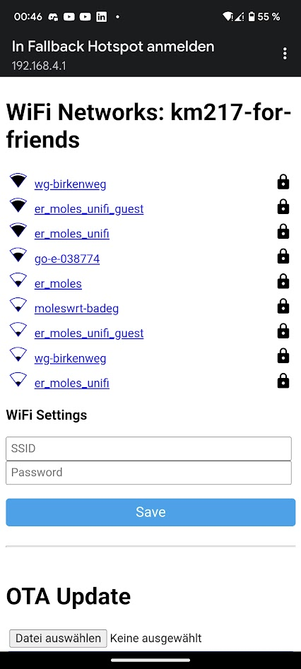
I configured the ESPhome firmware to run a captive portal after approx one minute. So, after powering the board, you could (after one minute) connect to the SSID „Fallback Hotspot“. Turn of your cellular internet (it disturbs the WiFi very often) and select the Fallback (password is "Z8zfajgxVvNw"). When WiFi of your phone is connected (sometimes you need some tries), a pop-up should ask you to sign in to the network. Follow this. It will present the portal of the ESPhome firmware and show you all WiFis it has found. Select the appropriate one and enter the password of this WiFi.
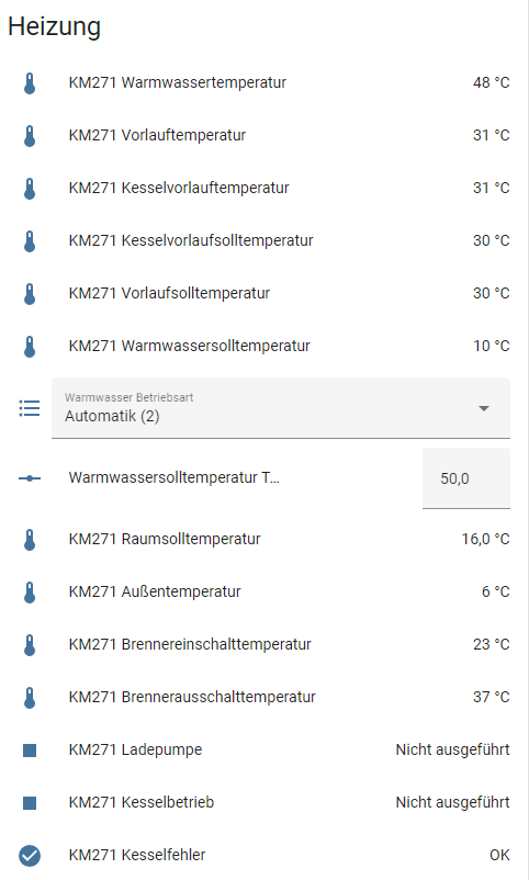
When the module is correctly connected to the network, it should soon show up as a new ESPhome board in your Home Assistant. Sometimes, you need to wait for a few minutes for the notification to show up. When adopted, you will see it in your ESPhome devices overview and can enter adjust the YAML to your needs. New sensor nodes will also take a few minutes to be shown sometimes.
The relevant part of the YAML is as follows:
esphome:
  name: km217-for-friends
  platform: ESP32
  board: esp32dev

# Enable logging
logger:

# Enable Home Assistant API
api:

ota:

wifi:
  ssid: "<YOUR WIFI SSID>"
  password: "<YOUR WIFI PASSPHRASE>"

  # Enable fallback hotspot (captive portal) in case wifi connection fails
  ap:
    ssid: "Fallback Hotspot"
    password: "Z8zfajgxVvNw"
Hardware Extensions
Exhaust Sensor
The Exhaust sensor is a simple 100 kOhm NTC-Resistor type, as you can order it e.g., at sensorshop24. In my case, I select the following options:
I realized, that the 25°C is very precise, but when the burner is working, my readings at 150°C are 15-20°C below the values the chimney sweeper is measuring with his calibrated device. The reason for this is most likely the characteristic curve, which is standardized for PT-Type (PT100, PT500, PT1000) temperature dependent resistors, but not for NTC. They are only defined at 25°C with their nominal value (here 100 kOhm), but not their B-value. But with ESPhome, you could easily correct this by filters for the sensor.
Other Settings
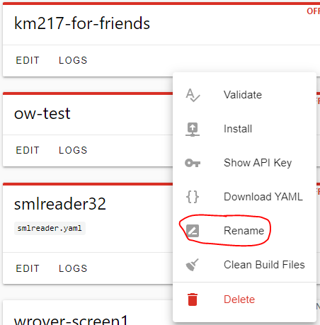
Renaming the module should be done using ESPhome GUI
For more detailed information, see my blog about the development of the module.
Using Arduino with MQTT
Coming soon 🙂
5V Supply bei 44 Volt und Website nicht erreichbar
Hi,
ich habe das Modul heute in Betrieb genommen und in Home Assistent integriert. Zwei Sachen wundern mich gerade:
– die „KM217 5V Supply“ wird zwischen 44,4 und 44,7 Volt angezeigt. Ist das nur ein Kommafehler? Dann wäre es aber auch zu wenig mit 4,4 Volt.
– Das Modul ist über seine IP-Adresse nicht per http erreichbar, also auch keine OTA Update Möglichkeit.
Hast du eine Idee dazu?
Vielen Dank und Grüße
Antwort von MolesBlog
Hallo Sebastian,
die viel zu hohe Spannung ist Absicht. Man muss den Sensor kalibrieren. Wie das geht… Spannung mit einem Multimeter messen, mit dem angezeigten Wert ins Verhältnis setzen (z.B. 4,95 / 44,5 = 0,111235) und damit den Multiplier im YAML multiplizieren. Der Grund ist, dass der ADC des ESP einfach grottig ist und ich den nicht „ab Werk“ sauber kalibrieren kann…
OTA-Updates macht man über das HA Add-On „ESPHome Builder“. Da taucht dann auch das Modul auf und man kann das YAML-File editieren.
Grüße,
Daniel
Funktioniert super, danke!
Vielen Dank für dieses tolle Projekt! Ich habe zwei der Boards gekauft und betreibe sie erfolgreich in Logamatic R2107 S0 Installationen in Kombination mit home Assistant.
Antwort von MolesBlog
Vielen Dank für die Rückmeldung. Freut mich, dass es Dir gefällt! Ich wünsche Dir noch viel Spaß mit dem kleinen Modul.
Kurze Frage?
Kann man einen bzw. 2 OneWire Temperatur Sensor(en) wie DS18B20 direkt an die Platine anschließen?
Antwort von MolesBlog
Ja, das geht. Je nachdem, welchen Versionsstand Deine Platine hat, musst Du nicht einmal etwas anpassen. Außerdem ist es noch sinnvoll, sich die Dokumentation (Schaltplan, ESPhome bzw. dewennis GitHub) genauer anzusehen. Support kann ich hier aus Zeitgründen nicht leisten.
11 Kommentare