OK, you’ll definitely believe, moles are crazy. You would ask, for what do you need a laboratory power supply that is controlled by your smart home (Home Assistant)? It’s easy, the underground battery storage needs special care, until I attached everything to my Victron MultiPlus-II. I just want the battery to be charged, when the grid prices are low.
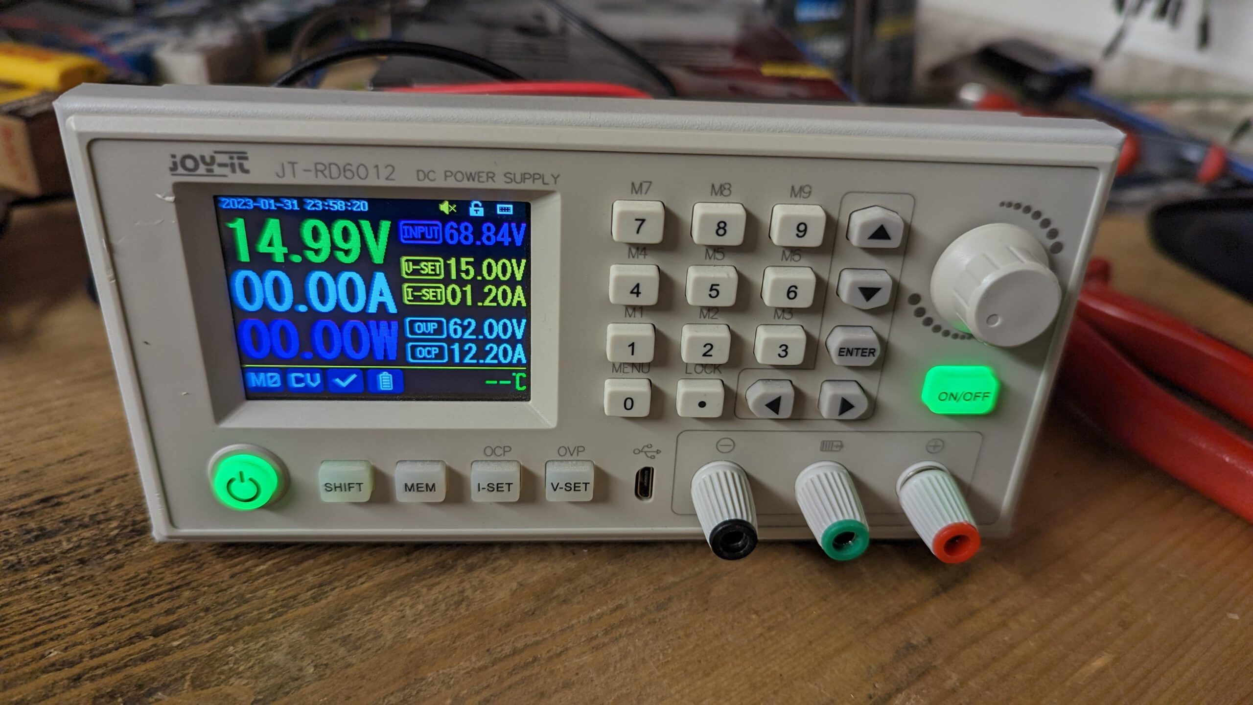
Let’s start over, what I have… I bought some Joy-IT JT-RD6012 (60V/12A) Lab Power Supply some month ago, to play around with the think batteries or at least to recharge my home storage, while the iCharger takes it’s power from the home storage or pushes it back when I do a discharge cycle on the think battery. Additionally, my server runs partly (with the redundant supply unit) on the UPS-side of the Victron.
Since the BMS shows already a significant difference between the cells, it is time to run a full charging cycle. But not with expensive energy during the day. The prices are low around 4 o’clock in the morning and even moles need to work during the day.
The lab supply already has a WiFi-Module mounted and I found a post, that the supply unit is controlled by simple modbus commands. But you can use whatever WiFi-Module you want, even a homebrewn one with ESP32. Just ensure to use 3.3V for the UART. Since I’m lazy (doing an own design) and had a module already installed, I decided to make some backup of the original firmware, put some ESPhome firmware on it and give it a try to control it via modbus commands. So, let’s start over…
First I opened the case and disassembled the front with the main unit.
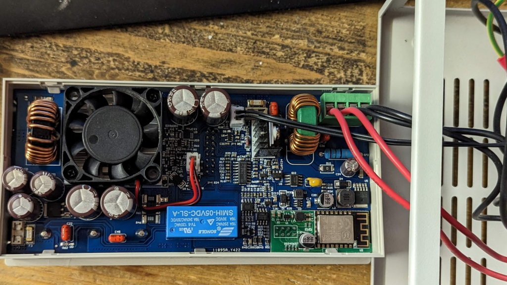
I detached the WiFi module…
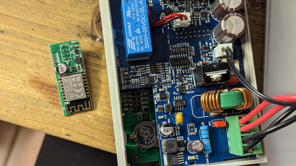
…and connected it to one of my programming adapters flying around in my lab.
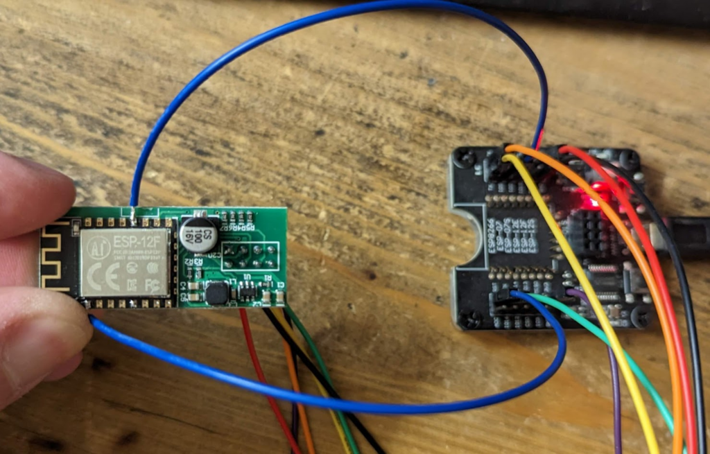
I also had to attach two other signals to the programmer, since they have not been broken out to the connector. Seems that Joy-IT uses a bootloader to update the firmware or a firmware update may even not be intended…
When you now try to connect to the ESP reading the flash_id, you get the following:

The chip_id gives the following:

With knowing the flash size (from the flash_id command), we can decide on the read_flash command (4MB = 0x400000) to take a backup of the original firmware (this is just boring, because it simply does not work well with Joy-IT application). The read-out will take about 5 minutes:

The binary that I did extract is the following, in case you bricked your module 🙂
Now we will upload some ESP firmware. Since initial programming with ESPhome did not connect to the module, I downloaded it for manual flashing (modern image format) and used esphome-flasher to get it onto the device (later you can just use OTA):

The ESP-12F has the following pin-out:

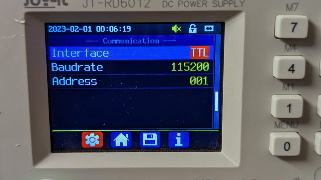
Pins RXD0 is GPIO3, TXD0 is GPIO1 (we need this later for ESPhome config of the UART component). To get the module working in the power supply, you need to get rid of the EN-pin of the header. Otherwise, the module only gets enabled, when WiFi is selected in the menu, but then, the interface is not Modbus compatible. We need to configure it to TTL.
A very basic ESPhome YAML to control the basic functions of your power supply could look like this:
esphome:
  name: rd6012-supply

esp8266:
  board: esp01_1m

# Enable logging
logger:
  baud_rate: 0

# Enable Home Assistant API
api:
  encryption:
    key: "<YOUR_ENCRYPTION_KEY>"

ota:
  password: "<YOUR_OTA_KEY>"

wifi:
  ssid: !secret wifi_ssid
  password: !secret wifi_password

uart:
  id: uart_bus
  baud_rate: 115200
  tx_pin: 1
  rx_pin: 3

#stream_server:
#  uart_id: uart_bus
#  port: 3001

modbus:
  id: modbus1

modbus_controller:
  - id: RD6012
    ## the Modbus device addr
    address: 0x1
    modbus_id: modbus1
    setup_priority: -10
    update_interval: 10s

number:
  - platform: modbus_controller
    modbus_controller_id: RD6012
    name: "RD6012 Voltage set value"
    id: rd6012_voltage_set_value
    register_type: holding
    address: 0x0008
    unit_of_measurement: "V"
    value_type: U_WORD
    min_value: 0.00
    max_value: 61.10
    step: 0.01
    multiply: 100

  - platform: modbus_controller
    modbus_controller_id: RD6012
    name: "RD6012 Current set value"
    id: rd6012_current_set_value
    register_type: holding
    address: 0x0009
    unit_of_measurement: "A"
    value_type: U_WORD
    min_value: 0.00
    max_value: 12.10
    step: 0.01
    multiply: 100

sensor:
  - platform: modbus_controller
    modbus_controller_id: RD6012
    name: "RD6012 Voltage actual value"
    id: rd6012_voltage_actual_value
    register_type: holding
    address: 0x000A
    unit_of_measurement: "V"
    value_type: U_WORD
    accuracy_decimals: 2
    filters:
      - multiply: 0.01

  - platform: modbus_controller
    modbus_controller_id: RD6012
    name: "RD6012 Current actual value"
    id: rd6012_current_actual_value
    register_type: holding
    address: 0x000B
    unit_of_measurement: "A"
    value_type: U_WORD
    accuracy_decimals: 2
    filters:
      - multiply: 0.01

  - platform: modbus_controller
    modbus_controller_id: RD6012
    name: "RD6012 Power actual value"
    id: rd6012_power_actual_value
    register_type: holding
    address: 0x000C
    unit_of_measurement: "W"
    value_type: U_DWORD
    accuracy_decimals: 2
    filters:
      - multiply: 0.01

switch:
  - platform: modbus_controller
    modbus_controller_id: RD6012
    name: "RD6012 Output enable"
    id: rd6012_output_enable
    register_type: holding
    address: 0x0012
I don’t want to miss, telling you a basic drawback of this approach. When there is modbus communication, the hardware keys are just disabled. So, do not set your update interval to narrow or you can not configure the stuff with the hardware keys anymore. I read something about an alternative firmware for the power supply itself, that does not suffer this restriction, but I also do not want to brick the supply. I would just disable the ESPhome component, if it disturbs me too much.
References and Links
Some other articles that helped me getting quickly through this:
Schreibe einen Kommentar