
Lie Down and Grow a Fillet: A Support-Free Haubenturm for the Hager 80SL
A new cover for my old Hager 80SL meter cabinet came with screws half a millimetre too fat for the old hood towers. The towers are no longer made, the printables models drown in support, so I drew my own in FreeCAD.
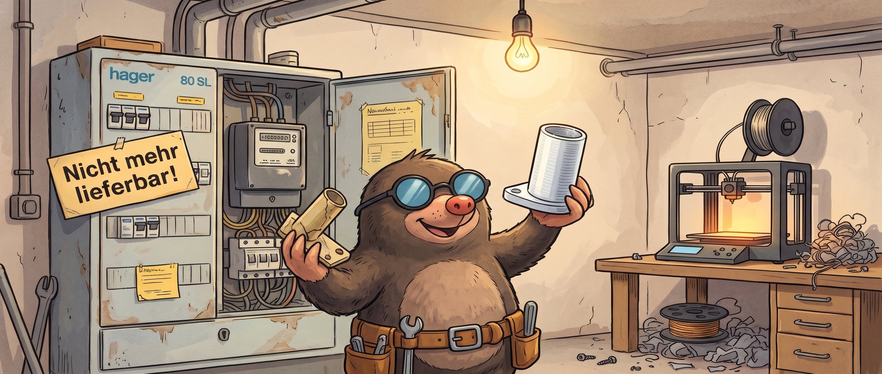
Every burrow has one piece of infrastructure nobody thinks about until it gets in the way. In mine, that piece is about four centimetres tall, the colour of old ivory, and it lives behind the covers of the meter cabinet. It is called a Haubenturm, a "hood tower", and its one job is to hold the screw that keeps a cover in place.
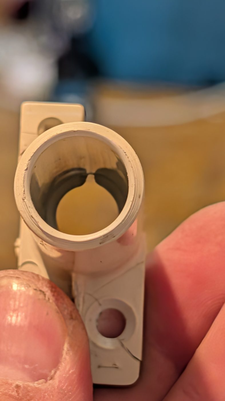
The cabinet is a Hager 80SL, a perfectly good German meter cabinet from an era when things were built to outlive their owners. Recently I upgraded the pre-meter area: out went the old NH00 fuses, in went a selective main circuit breaker (SLS) and a surge protection device (SPD). That needs a different cover, and that cover, miraculously, Hager still sells.
Half a Millimetre of Trouble
The new cover came with new screws. White ones, shiny, modern. And with a thread outer diameter about 0.5 mm larger than the old ones.
Half a millimetre doesn't sound like much. In a plastic thread it is the difference between "screws in nicely" and "jams solid after two turns while the tower creaks in a worrying tone". The old towers simply don't take the new screws.
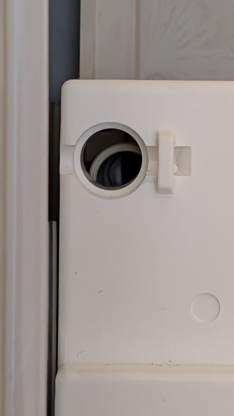
So: new towers. And the replacement part, as any mole who has tried to buy spares for a 25-year-old cabinet will guess, is nicht mehr lieferbar. No longer available. Which, in my workshop, is not a dead end. It is a print job.
Attempt 1: Somebody Must Have Done This Already
Somebody had. Printables has a set of Hager F82N (40 mm) and F82K (80 mm) towers for the 80/90 SL by Labfruits, plus at least one other variant. Download, slice, print, done. In theory.
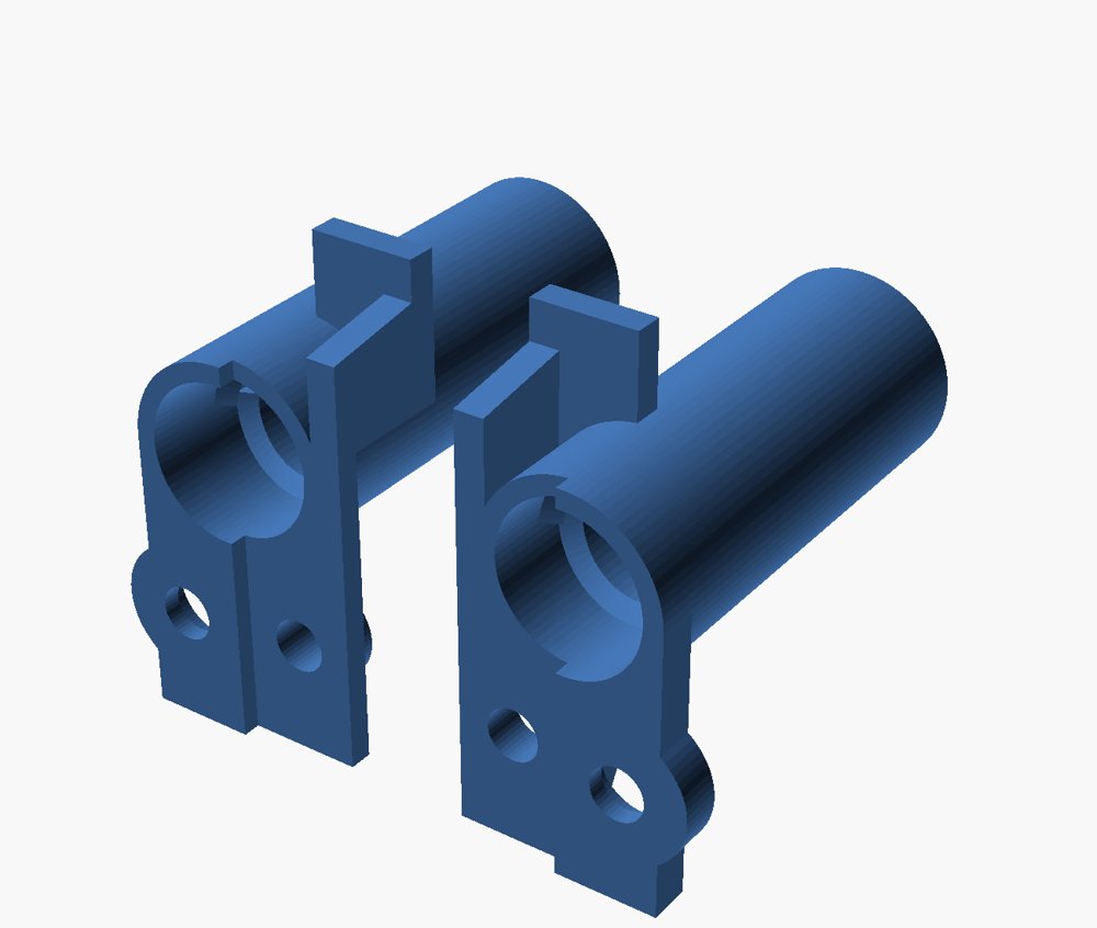
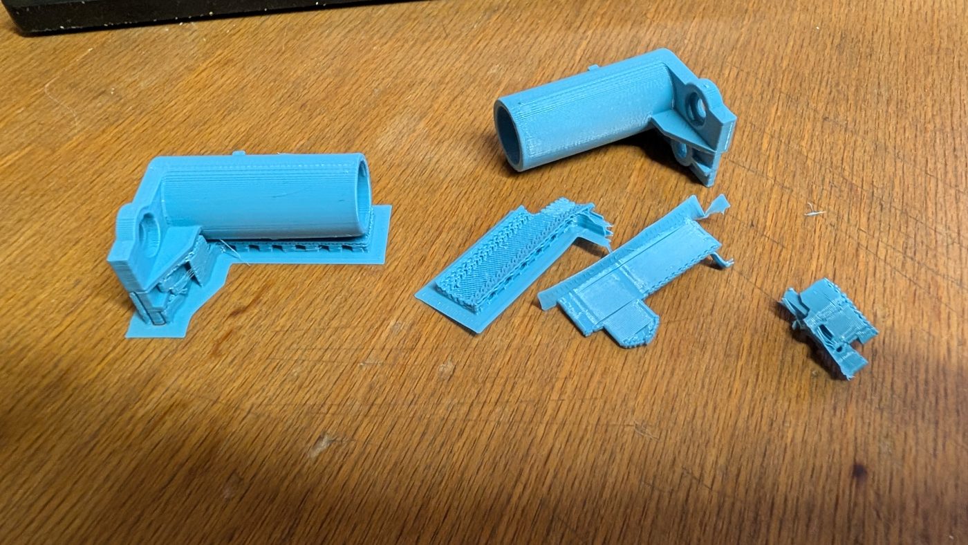
In practice, these models have overhangs in all the wrong places: inside the tube, under the plate, around the screw holes. The slicer's answer to overhang is support material. Lots of it. Getting it out of a 12 mm tube with a thread in it is the kind of activity that teaches patience, or at least vocabulary. The result after excavation:
They do look like the original once you've cleaned them up:
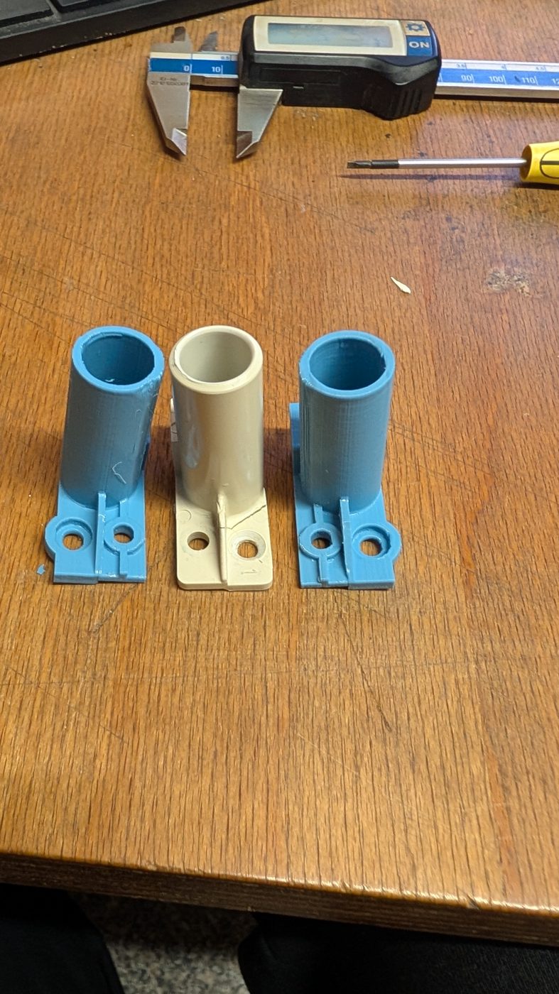
They work. But every print means another round of support archaeology, and support scars inside a thread are exactly what you don't want.
Attempt 2: Ask the AI Mole
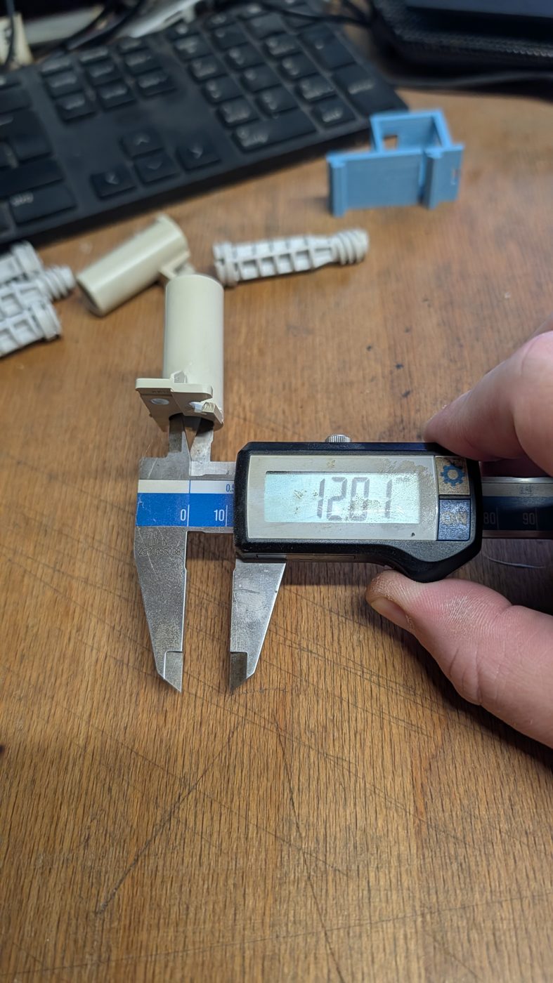
Before drawing anything myself, I grabbed the calipers, measured the original to the hundredth, took photos of everything, and asked Claude for a parametric replacement.
What came back was an honestly impressive OpenSCAD file: all the measured values in a Customizer block, a modelled internal thread with 45° flanks, and teardrop-shaped holes so that horizontal bores bridge without support.
pin_od        = 11.74;  // measured outer diameter of the NEW threaded pin
thread_clear  = 0.40;   // diametral clearance between pin and internal thread
thread_pitch  = 3.0;    // pitch, estimated from a photo (~3 mm)
flank_angle   = 45;     // 45° = nicely printable
bore_d        = 12.35;  // tube inner diameter above the thread, measured
plate_t       = 2.47;   // measured
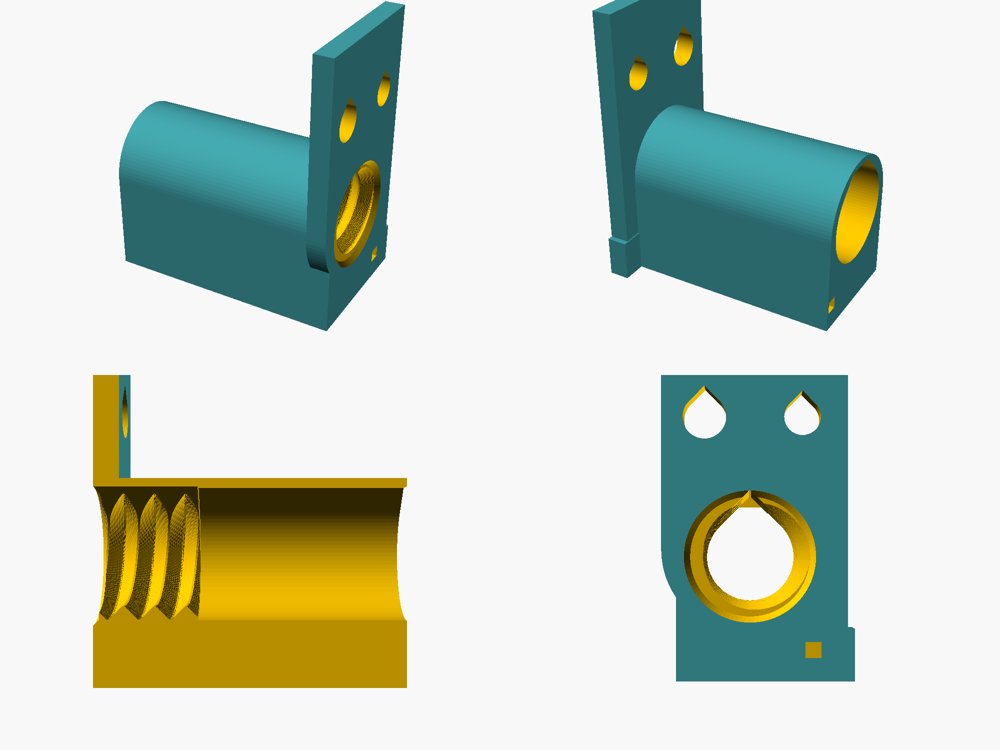
A great head start on the numbers. But for the actual part, I wanted my hands on the geometry, so I opened FreeCAD.
Attempt 3: Lie Down and Grow a Fillet
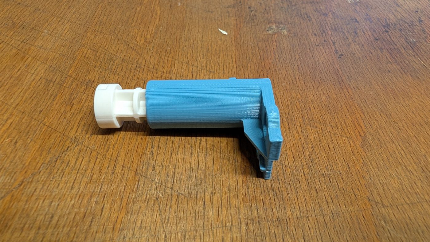
The trick is in the print orientation. I print the tower lying down, tube horizontal. That sounds like it would make everything worse, but in this orientation the rounded corner of the plate around the tube sits right above the print bed. Nothing else is in the way there.
So I simply extended that rounding straight down to the bed. The tube now rests on a solid web of plastic instead of hanging in the air. That web does two jobs at once:
- It replaces the support. There is nothing left that floats. The tube grows up out of the web, layer by layer.
- It reinforces the part. The joint between tube and plate, which takes the load when the cover is screwed on, is now backed by solid material instead of a thin wall.
Support material you throw away. This one stays and earns its keep.
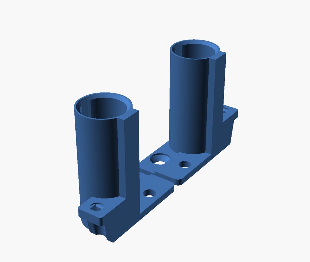
The model is plain PartDesign: a pad for the plate, pockets and holes for the cutouts, a few fillets and 45° chamfers, and the internal thread cut with subtractive helices running along the bore. The towers come as a left and a right version, and getting there is less simple than it sounds. More on that below.
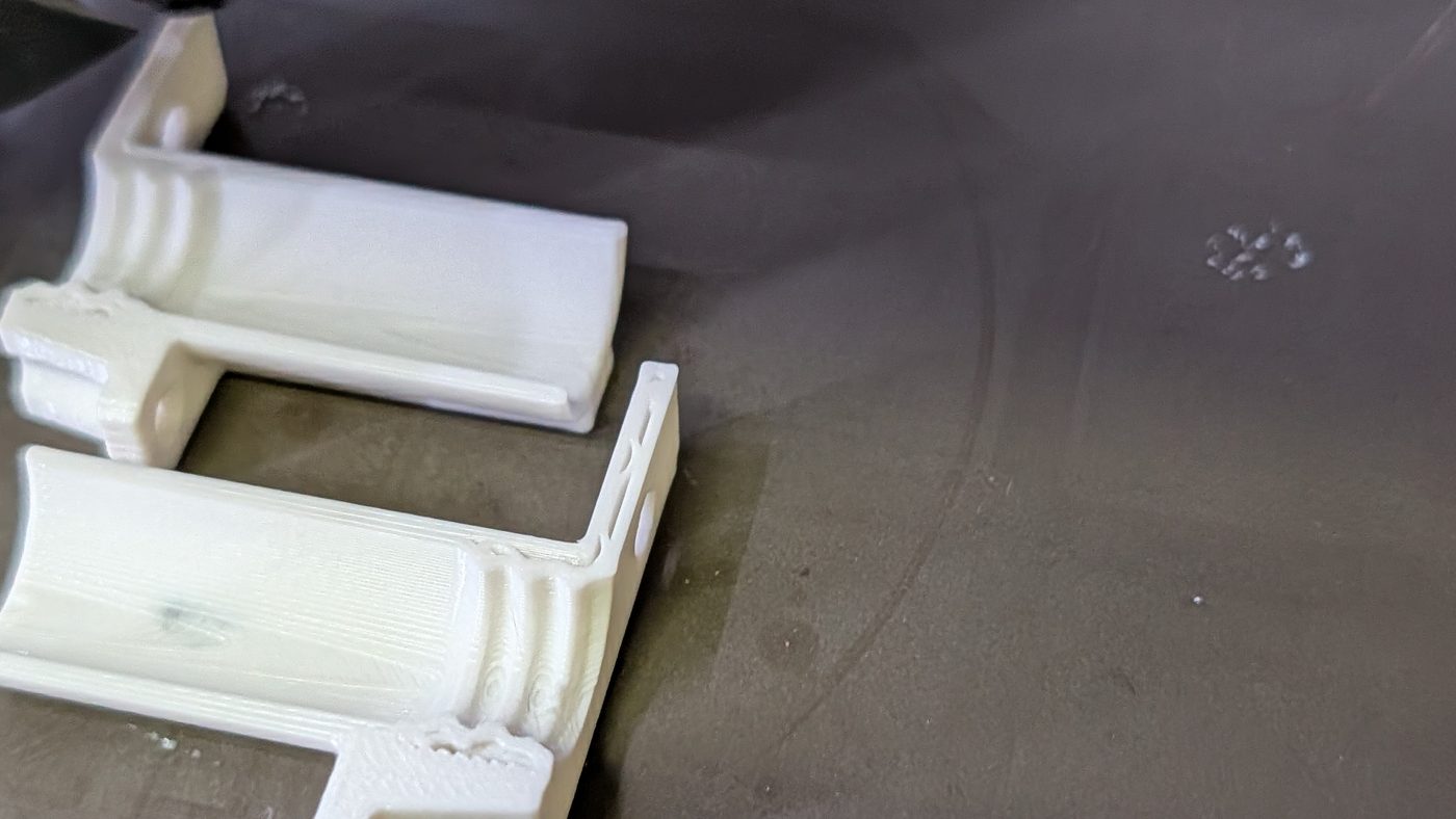
Here they are on the bed, caught mid-print. The half-finished tube shows the thread grooves from the inside, and you can see the plate's rounding running down into the bed:
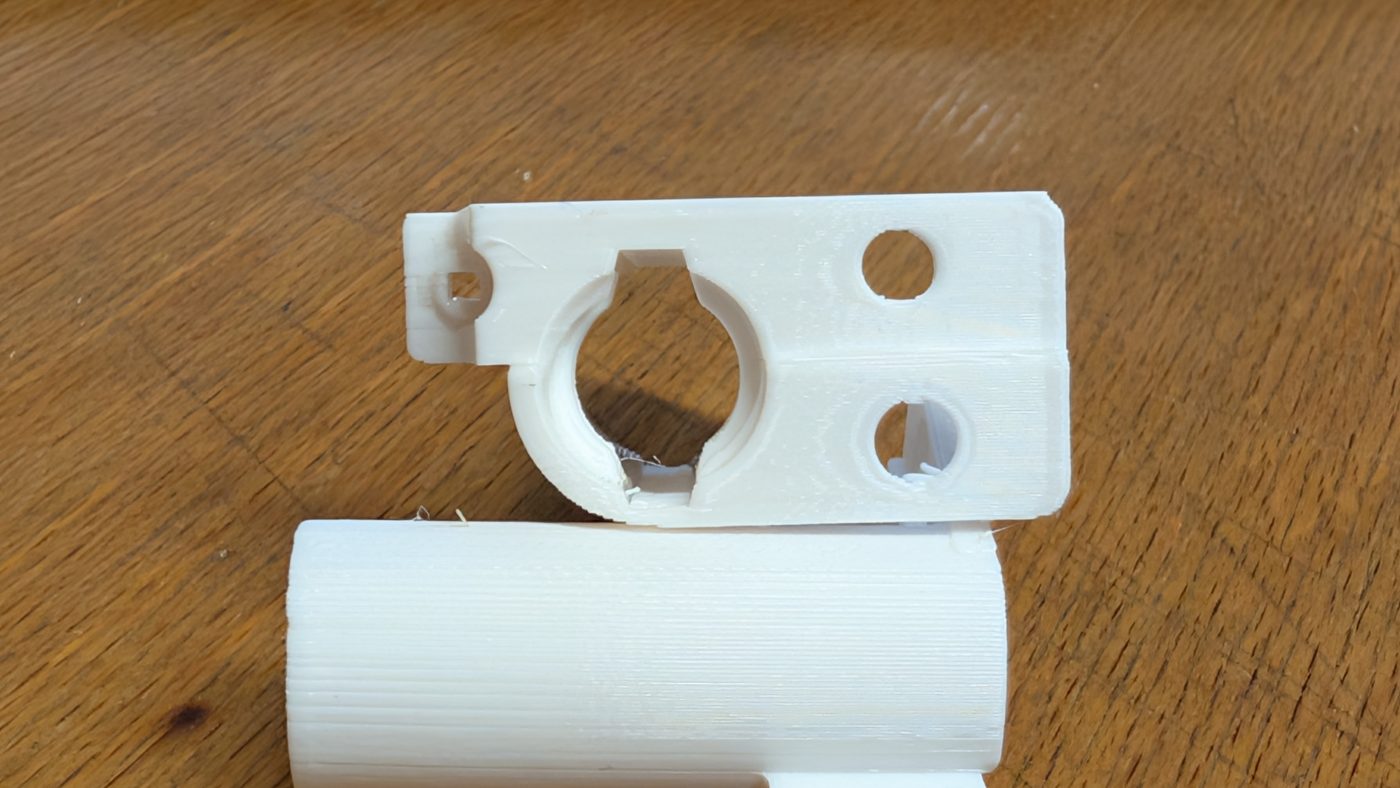
And the finished part, looking at the plate side with the threaded bore and the two screw holes:
Forget Teardrops, Cut a Slot
Look closely at that bore: it isn't round. Printed lying down, the threaded bore is a horizontal hole, and the top of a horizontal hole is the classic overhang. The usual fix is a teardrop, the one the AI draft used: let the top of the circle run up into a 45° point. That works, but the point pokes into the thread, and the screw has to cut its way through it.
My trick is simpler: cut a rectangular slot out of the top of the bore instead. The slicer then prints the roof of that slot as a perfectly straight horizontal bridge, and that bridge sits outside the bore diameter, where it never touches the screw.
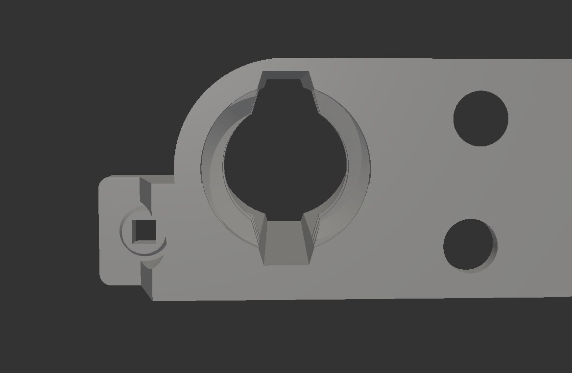
Then I just made it symmetric and cut the same slot at the bottom. That has nothing to do with printing, and everything to do with screwing: with two slots the screw finds its way in more easily and doesn't wedge itself into the thread nearly as quickly. Turns out half a millimetre of extra screw is a lot less dramatic when the thread has somewhere to breathe.
| Printables models | My FreeCAD model | |
|---|---|---|
| Support material | Lots, also inside the tube | None |
| Post-processing | Support archaeology | Pull it off the bed |
| Tube-to-plate joint | Thin wall | Backed by the extended rounding |
| Thread | One size | Tuned for the new, fatter screws |
The Thread Is the Hard Part
The tower is easy. The thread is where the hours go, and where the prints pile up.
Remember the AI draft's thread_pitch = 3.0? I believed that too, for a while. The screw looks like it has a single thread with a 3 mm pitch. It doesn't. It has two interleaved threads with a 6 mm pitch each, a two-start thread. Count the crests along the screw and you get one every 3 mm, but follow a single groove around and it advances 6 mm per turn. A single-start 3 mm thread in the tower simply doesn't match that screw, no matter how much clearance you give it. It took me several prints to notice.
The profile wasn't trivial either. The thread contour isn't a neat textbook triangle, so getting the flanks right so the screw turns smoothly without wobbling took another couple of rounds.
The Mirror Trap
Then there's left and right. The cabinet needs both versions of the tower, and CAD makes that look like one click: mirror the part, done. Except a mirror flips everything, including the helix. Mirror a right-hand thread and you get a beautiful, perfectly printable left-hand thread, which is completely useless with a right-hand screw.
The order that works:
- Model the tower completely, except for the thread.
- Create the mirror image of that thread-less body.
- Cut a right-hand thread into each of the two bodies separately.
That's why the FreeCAD file has more than one set of subtractive helices in it. It's not redundancy, it's the price of not wanting a left-handed cabinet.
Done, and Back on the Wall
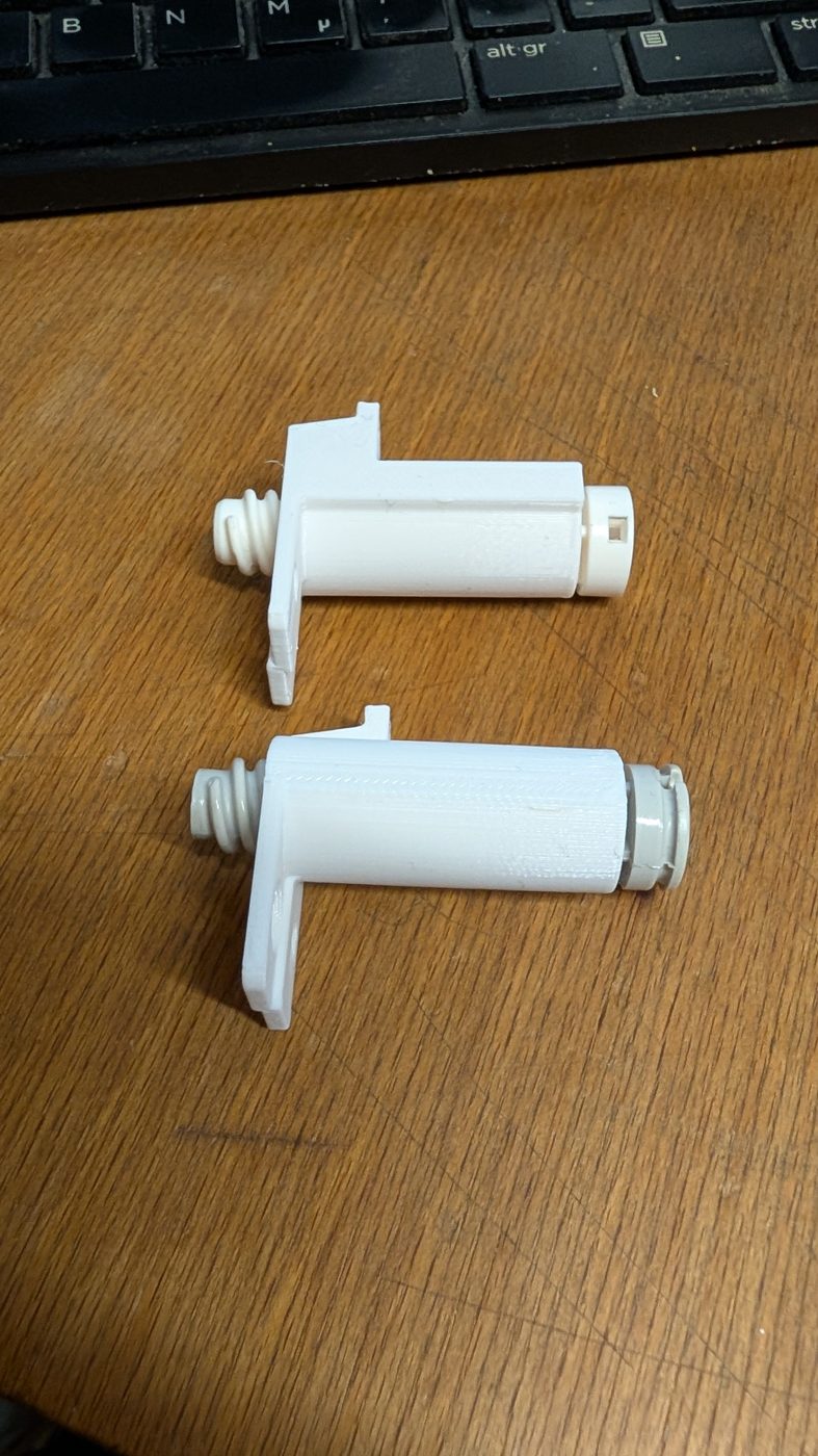
The finished towers, with screws in and ready to hold the new cover for another couple of decades, or at least until the next mole needs a blog post:
What I learned, in order of how long it took me to learn it:
- Half a millimetre is a lot. Spare parts that are "compatible" can still be just different enough to jam.
- Look at the print orientation before you add support. Lying down looked like the hard way, but it opened up room for a feature that replaces the support entirely.
- The best support is the one you keep. Extending an existing rounding to the bed costs a few grams of filament and makes the part stronger.
- Count the thread starts, not just the crests. A two-start 6 mm thread looks exactly like a single 3 mm one until you print it wrong.
- Never mirror a thread. Mirror the body, then cut a right-hand thread into each side.
I'll put the model up on Printables soon, so if your Hager 80SL is also short a tower, you won't have to dig the same tunnel twice.